Apparatus and method for circular vortex air flow material grinding

a technology of vortex flow and apparatus, which is applied in the direction of gas current separation, solid separation, grain milling, etc., can solve the problem that landfills often have limited space, and achieve the effect of simplifying the construction of the uni

Inactive Publication Date: 2002-03-07
VORTEX DEHYDRATION TECH
View PDF3 Cites 54 Cited by
  • Summary
  • Abstract
  • Description
  • Claims
  • Application Information

AI Technical Summary

Benefits of technology

[0010] The present invention also is directed to a material grinding method which comprises the steps of: (a) providing an upper enclosure with at least one hole of a predetermined size formed therethrough between exterior and interior sides thereof and oriented so as to extend between and at an acute angle relative to the exterior and interior sides so as to provide flow communication between the exterior side thereof and an upper interior chamber thereof; (b) providing a lower enclosure below and in tandem with the upper enclosure and having an inverted conical configuration such that an lower interior chamber of the lower enclosure is substantially continuous and in flow communication with the upper interior chamber of the upper enclosure; (c) delivering material to be ground into the upper interior chamber of the upper enclosure through an upper end thereof; (d) supplying a flow of air, such as in a compressed state, through the hole in the upper enclosure into the upper interior chamber thereof to along a flow path extending about the interior side of the upper enclosure; and (e) exhausting air from the upper interior chamber of the upper enclosure through the upper end thereof such that the supplying of air and the exhausting of air coact with the hole in the upper enclosure and with the upper and interior chambers to create a circular vortex flow of air within the upper and lower interior chambers of the upper and lower enclosures that causes grinding and drying of material substantially in the upper interior chamber of the upper enclosure, downward travel of ground material through the lower interior chamber of the lower enclosure and downward discharge of the ground material from the lower interior chamber of the lower enclosure through an open lower end thereof, the lower interior chamber of the lower enclosure being provided with an inverted conical shape which augments the circular vortex flow of air and material in the upper and lower interior chambers of the upper and lower enclosures.
[0030] The upper enclosure 12 also includes at least one and, preferably, a plurality of deflection plates 90. Each deflection plate 90 has a substantially angular configuration and is mounted to the upper annular sidewall 24 of the upper enclosure 12 at the interior side 12B thereof and adjacent to a respective one of the air holes 56 of the upper enclosure 12. Each deflection plate 90 functions to slightly deflect the flow of air circulating within the upper interior chamber away from the air hole 56 as it passes the air hole 56 so as to not disrupt the incoming air flow from the hole 56 into the upper interior chamber 34 of the upper enclosure 12. The angular configuration of the deflection plate 90 provides a gap between it and the upper annular sidewall 24 to allow the maximum amount of air to flow unrestricted into the upper interior chamber 34.
[0031] Referring to FIG. 6A, a "C" shaped shim plate 200 is preferably used in the invention to direct air flow. Preferably, this plate is 8" by 10" structure with a 2" wide vertical wall on one side, a 1" wide horizontal wall on two opposite sides, and a opening on the fourth side as shown in FIG. 6A. The shim plate 200 is placed on the inside diameter of the grinding chamber 12 between the deflector plate 90 and the grinding chamber 12. The shim plate 200 is very thin, preferably having a thickness of 55 thousandths of an inch if 3 orifices are used and 45 thousandths of an inch if 4 orifices are used. Installing the shim plate 200 simplifies the construction of the unit as it eliminates the need for the adjustable plate mechanism 60 detailed in FIGS. 4 and 5. FIGS. 6B and 6C shows show an overview and vertical cross-section, respectively, of the manifold and air hole when the shim plate (shaded) is utilized to direct air flow.
[0038] The compressed air introduced into the upper interior chamber 34 of the upper enclosure 12 may have a preselected pressure that falls within a wide range of from about 10 to about 600 pounds per square inch (psi). The compressed air may have a velocity that falls within a wide range of from about 5 to about 12,000 cubic feet per minute (cfm). The compressed air also may have a temperature which may be varied. The temperature of the compressed air may be raised, such as by use of a heat exchanger unit (not shown) or the like, to enhance the grinding and drying of the material. The temperature of the air may fall within a wide range of about 40.degree. F. to about 900.degree. F. Steam can also be used to heat the compressed air. The steam may be at a temperature falling within a wide range of about 212.degree. F. to 2000.degree. F. This will greatly enhance the drying process as well as increase the shearing force of the compressed air. Steam may also be used to operate the apparatus 10 at a specific pressure, temperature and cubic feet per minute.

Problems solved by technology

Landfills often have limited space.
Problems exist with this arrangement in that the upper portion of the cyclone chamber is cylindrical shaped and separated from the grinding chamber so it does not augment a vortex air flow created in the grinding chamber.

Method used


Image

  • Apparatus and method for circular vortex air flow material grinding
  • Apparatus and method for circular vortex air flow material grinding
  • Apparatus and method for circular vortex air flow material grinding

Examples


Embodiment Construction

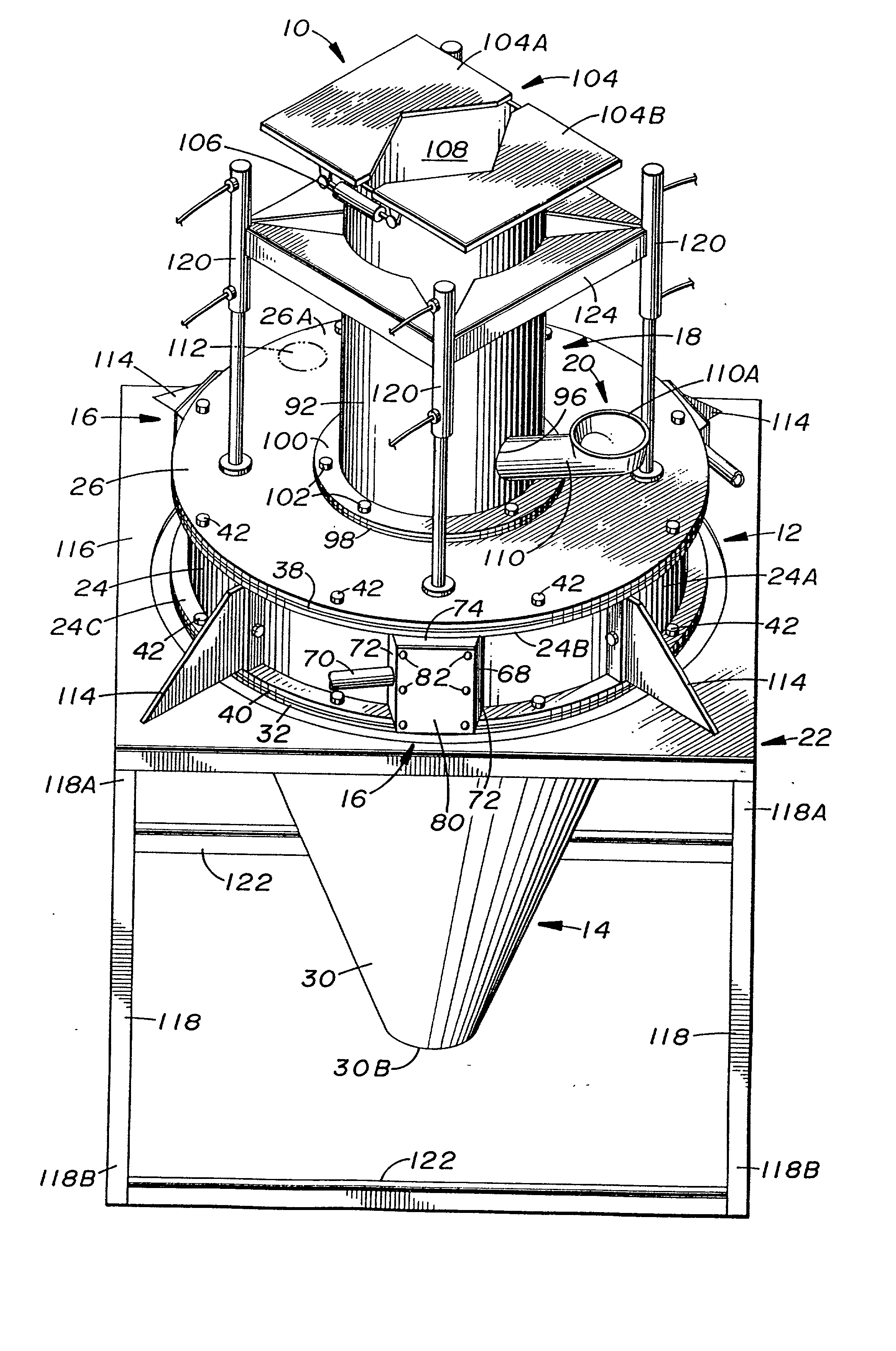
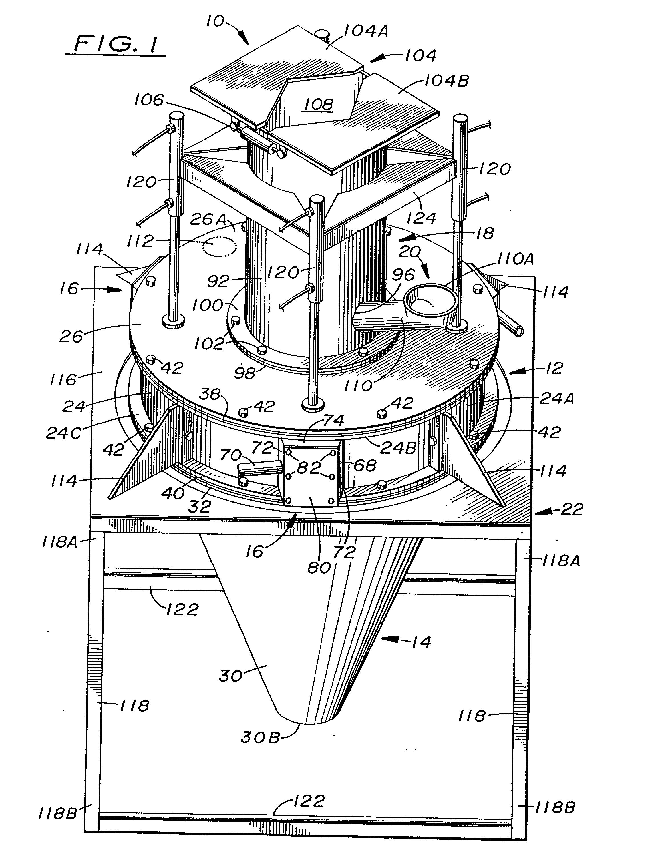
[0056] A four foot diameter grinding apparatus 10 was assembled as detailed above. The specifications for various parts used therein are set forth below:

[0057] The adjustable damper 104 is 22" square plate with a 0.24" thickness. The preferred setting is fully open when the exhaust pipe 92 is in its preferred setting (see next paragraph).

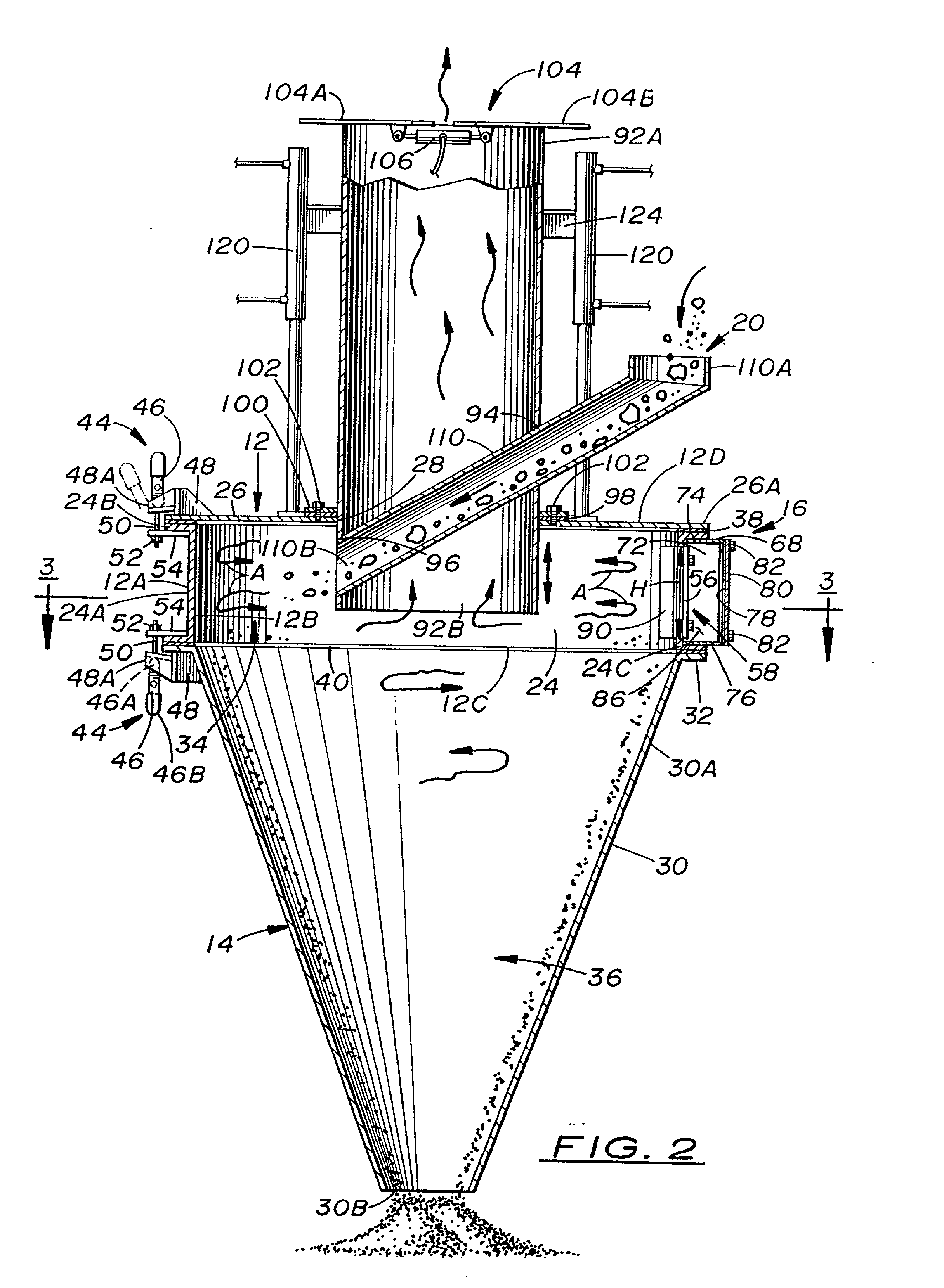
[0058] The adjustable exhaust pipe 92 is 20" OD (outside diameter) and 48" long. Accordingly, the opening 28 in the top cover 26 of the upper grinding chamber 12 is 20 inches in diameter. The adjustable exhaust pipe 92 can be moved vertically by loosening legs 120 and sliding the exhaust pipe through the annular seal 98 to the desired level. The annular seal 98 is then secured into place by a 3" wide flange 100 with and ID (inside diameter) of 20" and an OD of 26". The preferred setting is to lower the exhaust pipe 92 to a depth parallel to the seam joining the grinding chamber 12 to the lower enclosure 14.

[0059] The hopper feed tube 110 is 5" OD tu...


PUM


Abstract

A material grinding apparatus (10) includes an annular upper enclosure (12) defining an upper chamber (34) into which material to be ground is introduced from above, a conical lower enclosure (14) defining a lower chamber (36) and supported in tandem with the upper enclosure (12), and one or more angled slots (56) defined in the sidewall of the upper enclosure (12) through which compressed air is introduced relatively circumferentially into the upper chamber (34) so as to generate a circular vortex flow of air and material in the upper enclosure (12) for grinding and drying to take place. The air flow is exhausted by a pipe (92) through an upper end of the upper enclosure (12) and the dried ground material is discharged through an open lower end of the lower enclosure (14). The lower enclosure (14) is a downward continuation and extension of the upper enclosure (12) so as not to extend upwardly into nor past the upper chamber (34) thereof.

Description

[0001] This application is a continuation-in-part of U.S. patent application Ser. No. 09 / 719,846, filed on Dec. 15, 2000, which, in turn, claims priority to U.S. Provisional Patent Application No. 60 / 125,570, filed on Mar. 23, 1999.[0002] The present invention generally relates to material grinding and, more particularly, is concerned with an apparatus and method for circular vortex air flow material grinding.[0003] Landfills often have limited space. In order to reduce the volume of space which discarded materials occupy in landfills, it is generally desirable to have an apparatus capable of grinding diverse materials typically disposed of in landfills. Two approaches have employed air in the grinding process. One approach involves the use of a large volume of air which is generated by a fan. The other approach involves the use of air at high velocity instead of large volume. A variety of grinding devices using air have been developed over the years.[0004] Representative examples o...

Claims


Application Information

Patent Timeline
Patent Type & Authority Applications(United States)
IPC IPC(8): B02C19/06
CPCB02C19/061
Inventor POLIFKA, FRANCIS D.
Owner VORTEX DEHYDRATION TECH
Why Eureka
Try Eureka