Adaptive vibrations control for servo systems in data storage devices
Inactive Publication Date: 2002-03-21
LENOVO (SINGAPORE) PTE LTD
View PDF0 Cites 33 Cited by
Summary
Abstract
Description
Claims
Application Information
AI Technical Summary
This helps you quickly interpret patents by identifying the three key elements:
Problems solved by technology
Method used
Benefits of technology
Benefits of technology
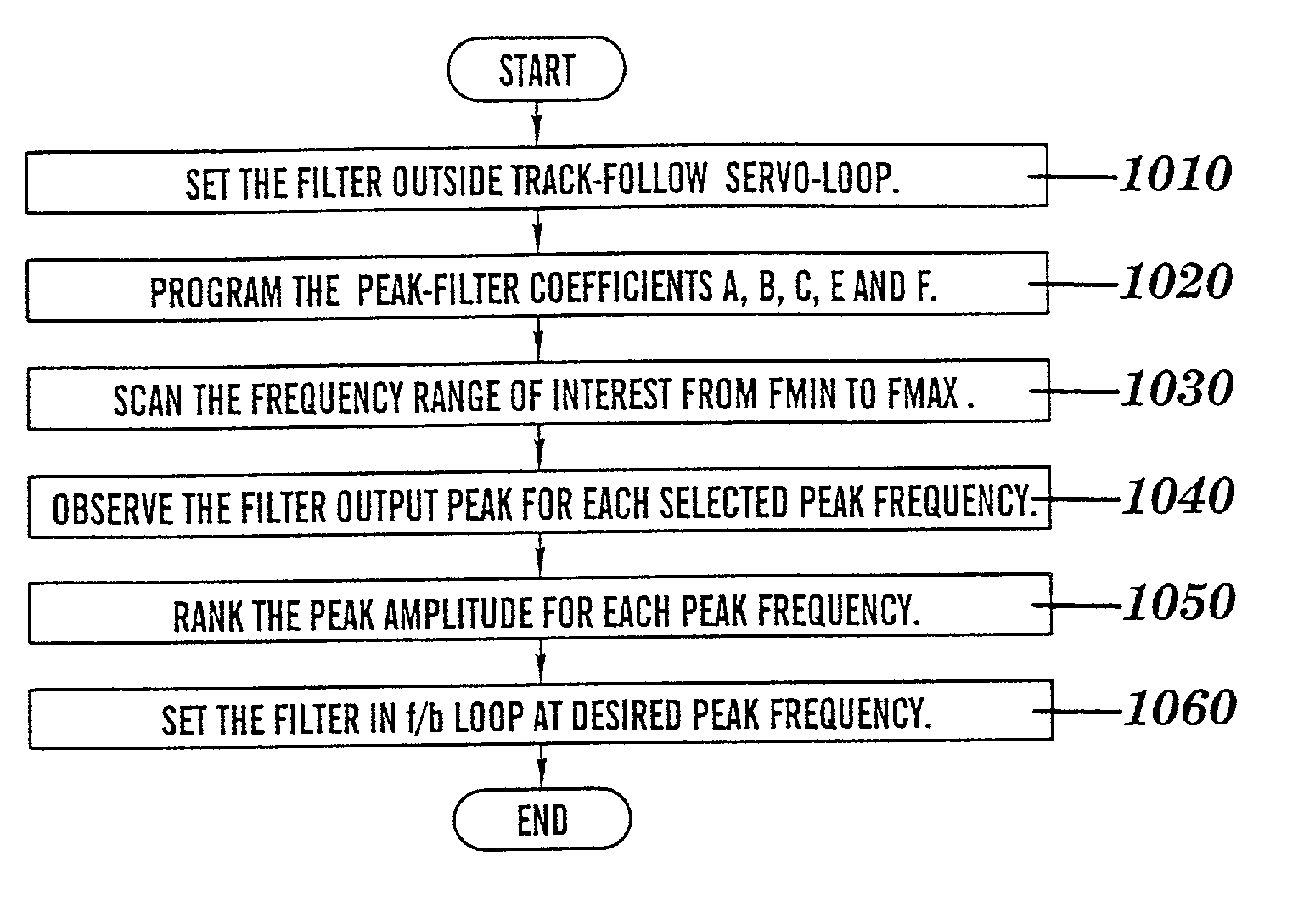
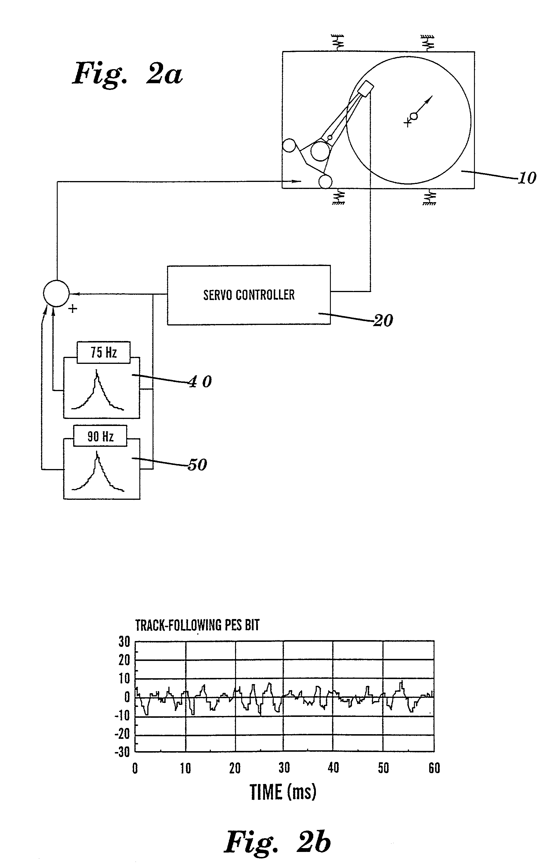
[0011] The present invention solves the periodic, cross vibration problem by implementing a two stepalgorithm which first detects the dominant cross vibration frequency, and then configures an optimal servo feedback solution. The information gathered during the detection process is used to configure a digital peak filter. The filter coefficients are tuned to compensate for the detected periodic vibration induced error. The servo algorithm uses a frequently updated initial condition vector to minimize the settleout time encountered due to the transient dynamics of the digital filter. Advantageously, no trigonometric computations, such as FFTs, are invoked in one aspect of the present invention, during the determination of the cross vibration frequency. Hence a low cost implementation in a microprocessor-based or specialized chip-based HDD servo controlsystem is provided by the present invention.
[0018] By utilizing the dual approach of first detecting, and then correcting for frequencies of vibration, and by providing the novel filter implementation structures herein, the present invention provides a solution for vibrations in data storage devices. These vibrations are often unpredictable, and the frequencies of vibration must therefore be detected and accounted for during real-time operation of the system. Further, the present invention provides low processing cost solutions to these problems, i.e., avoids FFT processing techniques, for the detection and filtering processes disclosed herein.
Problems solved by technology
With increases in track densities of Hard Disk Drives ("HDDs"), vibration sensitivity has become an acute problem.
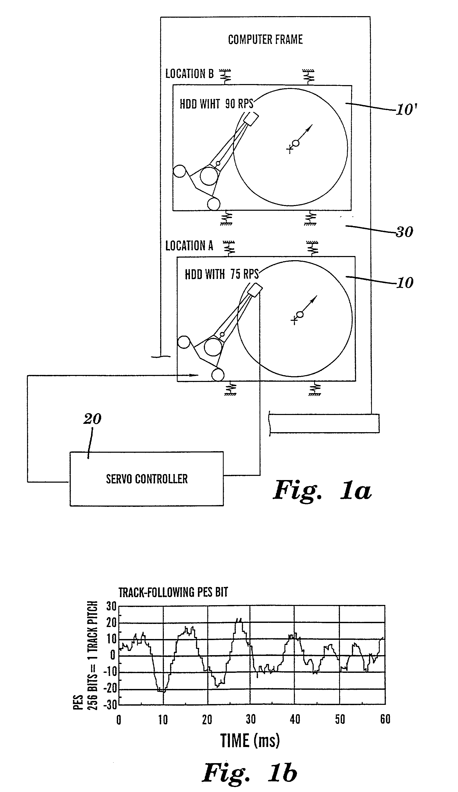
In computer servers or arrays, where multiple disk drives are mounted in a frame, vibrations from one drive may substantially affect neighboring drives.
Conventional servo systems can reduce the track-follow error by about 20 to 30 dB using the basic servo loop error rejection property, but this level of error rejection is no longer sufficient to make HDDs immune from adverse vibration effects.
This problem is expected to get worse with the accelerated growth of track densities in future products.
In portable computers, the 2.5" DASDs are subject to harsh non-operating conditions, and moderate operating conditions.
However, desk-top / server DASDs often operate in the presence of multiple vibration sources associated with other drives in a single computer frame.
Mechanical components such as spindle motor assemblies are not perfectly mass balanced, and may produce harmonic vibrations during operation.
When not compensated, a track-follow error of 10% of track pitch can be detrimental to a drive's soft and hard error rate performance.
However, it is often a challenge to convince customers to implement special mount designs to compensate for manufacturing imperfections of HDDs.
Positioning the read / write elements over small tracks is therefore a major challenge, especially in the presence of vibrations.
The run out at this frequency can result from either a physical shift of a disk with respect to its axis of rotation or from self vibration created by spindle motor mass imbalance.
However, when a frequency of cross vibration is unknown, such as that associated with another HDD in the same frame, a servo algorithm according to U.S. Pat. No. 5,608,586 cannot be designed and embedded in the drive prior to shipment.
Further, any solution should be implemented without major computational requirements since the cost constraints of HDDs usually preclude the use of a dedicated digital signal processor ("DSP") to perform complex or long arithmetic functions.
Method used
Image
Click on the blue label to locate the original text in one second.
Reading with bidirectional positioning of images and text.
PUM
Abstract
Methods and systems for detecting and correcting for undesirable vibrations impacting the servo systems in data storage devices. A detection technique is provided wherein a detection filter is configured to scan a position signal of the servosystem across a range of frequencies, and, at each respective scanned frequency, record an amplitude associated therewith. The recorded amplitudes are examined to determine whether any exceed a threshold, thereby locating a peak frequency of the vibration. Using the detected peak frequency of the vibration, a corrective filter is configured to operate about the peak frequency of vibration, thereby reducing its impact on the position signal in the servosystem. Optimum detection and correction filter structures are disclosed, as are techniques for addressing filter state vectors as initial conditions as the corrective filters are repeatedly engaged during successive settle-out and track follow cycles (between seeks), as are continuous adaptation techniques for changing vibration environments.
Description
[0001] The present invention relates to data storage devices. More particularly, the present invention relates to techniques for correcting the adverse effects of vibrations on servo systems in data storage devices.[0002] With increases in track densities of Hard Disk Drives ("HDDs"), vibration sensitivity has become an acute problem. Present generations of HDDs at densities of 10,000 tracks per inch ("TPI") already exhibit poor settleout and / or track-follow characteristics when subject to external vibrations. In computer servers or arrays, where multiple disk drives are mounted in a frame, vibrations from one drive may substantially affect neighboring drives. At least three types of external vibration sources are known: 1) periodic with relatively constant peak amplitude arising from spindle imbalance; 2) non-periodic arising from reaction torque generated by an actuator seek motion; and 3) random vibrations resulting from other unpredictable external events. For example, CD-ROMs a...
Claims
Application Information
Patent Timeline
Application Date:The date an application was filed.
Publication Date:The date a patent or application was officially published.
First Publication Date:The earliest publication date of a patent with the same application number.
Issue Date:Publication date of the patent grant document.
PCT Entry Date:The Entry date of PCT National Phase.
Estimated Expiry Date:The statutory expiry date of a patent right according to the Patent Law, and it is the longest term of protection that the patent right can achieve without the termination of the patent right due to other reasons(Term extension factor has been taken into account ).
Invalid Date:Actual expiry date is based on effective date or publication date of legal transaction data of invalid patent.
IPC IPC(8): G11B5/596G11B21/10G11B21/21G11B21/02
CPCG11B5/59611G11B21/106G11B21/02
InventorSRI-JAYANTHA, SRI MUTHUTHAMBYSHARMA, ARUNDANG, HIEN PHUKAGAMI, NAOYUKINAKAGAWA, YUZOTOKIZONO, AKIRAYONEDA, ISAO

