Initial power control for spread-spectrum communications

a spread-spectrum communication and power control technology, applied in the field of initial power control for spread-spectrum communications, can solve the problems of inability to track the maximum of function, inability to know the correct pilot spreading code phase, and excessive tim

a spread-spectrum communication and power control technology, applied in the field of initial power control for spread-spectrum communications, can solve the problems of inability to track the maximum of function, inability to know the correct pilot spreading code phase, and excessive tim

US20020036996A1Inactive Publication Date: 2002-03-28INTERDIGITAL TECH CORP

Image

  • Initial power control for spread-spectrum communications
  • Initial power control for spread-spectrum communications
  • Initial power control for spread-spectrum communications

Examples


Embodiment Construction

[0116] I. General System Description

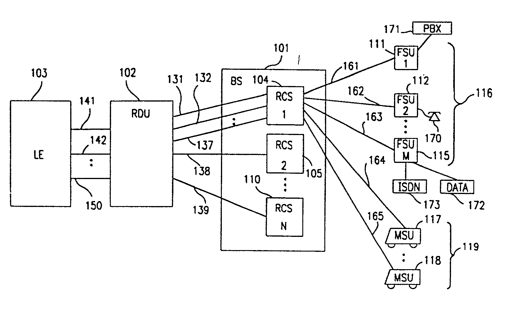
[0117] The system ofthe present invention provides local-loop telephone service using radio links between one or more base stations and multiple remote subscriber units. In the exemplary embodiment, a radio link is described for a base station communicating with a fixed subscriber unit (FSU), but the system is equally applicable to systems including multiple base stations with radio links to both FSUs and mobile subscriber units (MSUs). Consequently, the remote subscriber units are referred to herein as subscriber units (SUs).

[0118] Referring to FIG. 1, base station (BS) 101 provides call connection to a local exchange (LE) 103 or any other telephone network switching interface, such as a private branch exchange (PBX) and includes a radio carrier station (RCS) 104. One or more RCSs 104, 105, 110 connect to a radio distribution unit (RDU) 102 through links 131, 132, 137, 138, 139, and RDU 102 interfaces with LE 103 by transmitting and receiving cal...


PUM


Abstract

A code-division-multiple-access (CDMA) system employing spread-spectrum modulation. The CDMA system has a base station, and a plurality of subscriber units. The signals transmitted between the base station and subscriber unit use spread-spectrum modulation. The system and method transmits from the base station, a synchronization channel having a chip-sequence signal used by the plurality of subscriber units for synchronization. A first subscriber unit receives the synchronization channel, and determines timing from the synchronization channel. In order to initiate communications with the base station, the first subscriber unit transmits an access signal. The access signal has a plurality of power levels, which typically ramp up. The base station receives the access signal at a particular-power level. The base station then transmits to the first subscriber unit an acknowledgment signal. The first subscriber unit receives the acknowledgment signal, and transmits to the base station, a spread-spectrum signal.

Description

[0001] This application is a continuation-in-part to U.S. patent application Ser. No. 08 / 956,740 filed on Oct. 23, 1997; which is a continuation of U.S. patent application Ser. No. 08 / 669,775 filed on Jun. 27, 1996 which issued on Aug. 25, 1998 as U.S. Pat. No. 5,799,010; which is a continuation-in-part to U.S. Provisional Application Ser. No. 60 / 000,775 filed on Jun. 30, 1995. This application is also a continuation-in-part to U.S. patent application Ser. No. 09 / 721,034 filed on Nov. 22, 2000; which is a continuation of U.S. patent application Ser. No. 09 / 003,104 filed on Jan. 6, 1998 which issued on Jan. 30, 2001 as U.S. Pat. No. 6,181,949 B1; which is a continuation of U.S. patent application Ser. No. 08 / 670,162 filed on Jun. 27, 1996 which issued on Nov. 24, 1998 as U.S. Pat. No. 5,841,768. This application is also a continuation-in-part to U.S. patent application Ser. No. 09 / 304,286 filed on May 3, 1999; which is a continuation of U.S. patent application Ser. No. 08 / 671,068 fil...

Claims


Application Information

Patent Timeline
28 Mar 2002
Publication
US20020036996A1
IPC
G06F13/374; H03H17/02; H03H17/06; H04B1/707; H04B7/005; H04B7/26; H04J13/00; H04J13/04; H04L1/00; H04L5/14; H04L25/02; H04L27/00; H04L27/20; H04L27/233; H04N1/333
CPC
H03H17/0226; H03H17/0254; H03H17/06; H03H17/0607; H03H2218/06; H04B1/707; H04B1/7075; H04B1/70753
Inventors
OZLUTURK, FATIH M.; LOMP, GARY R.