Digital signal processing method, data recording and reproducing apparatus, and data recording medium that are resistant to burst errors

a digital signal processing and burst error technology, applied in the field of digital signal processing methods, data recording and reproducing apparatuses, and data recording media, can solve the problems of increasing affecting the accuracy of data correction, so as to increase the maximum burst error correctable length relatively easily, and increase redundancy

Inactive Publication Date: 2002-03-28
JVC KENWOOD CORP A CORP OF JAPAN
View PDF2 Cites 17 Cited by
  • Summary
  • Abstract
  • Description
  • Claims
  • Application Information

AI Technical Summary

Benefits of technology

0011] In view of the foregoing, it is an object of the present invention to provide a digital signal processing method, a data recording and reproduc...

Problems solved by technology

Recently, data recording media have become denser.
On such a high-density disk, a defect developed during disk manufacturing or dust or a scratch during use, if any, would be twice as large as that on the DVD in view of the relative data length.
Therefore, if there is a random error, the length o...

Method used


Image

  • Digital signal processing method, data recording and reproducing apparatus, and data recording medium that are resistant to burst errors
  • Digital signal processing method, data recording and reproducing apparatus, and data recording medium that are resistant to burst errors
  • Digital signal processing method, data recording and reproducing apparatus, and data recording medium that are resistant to burst errors

Examples


first embodiment

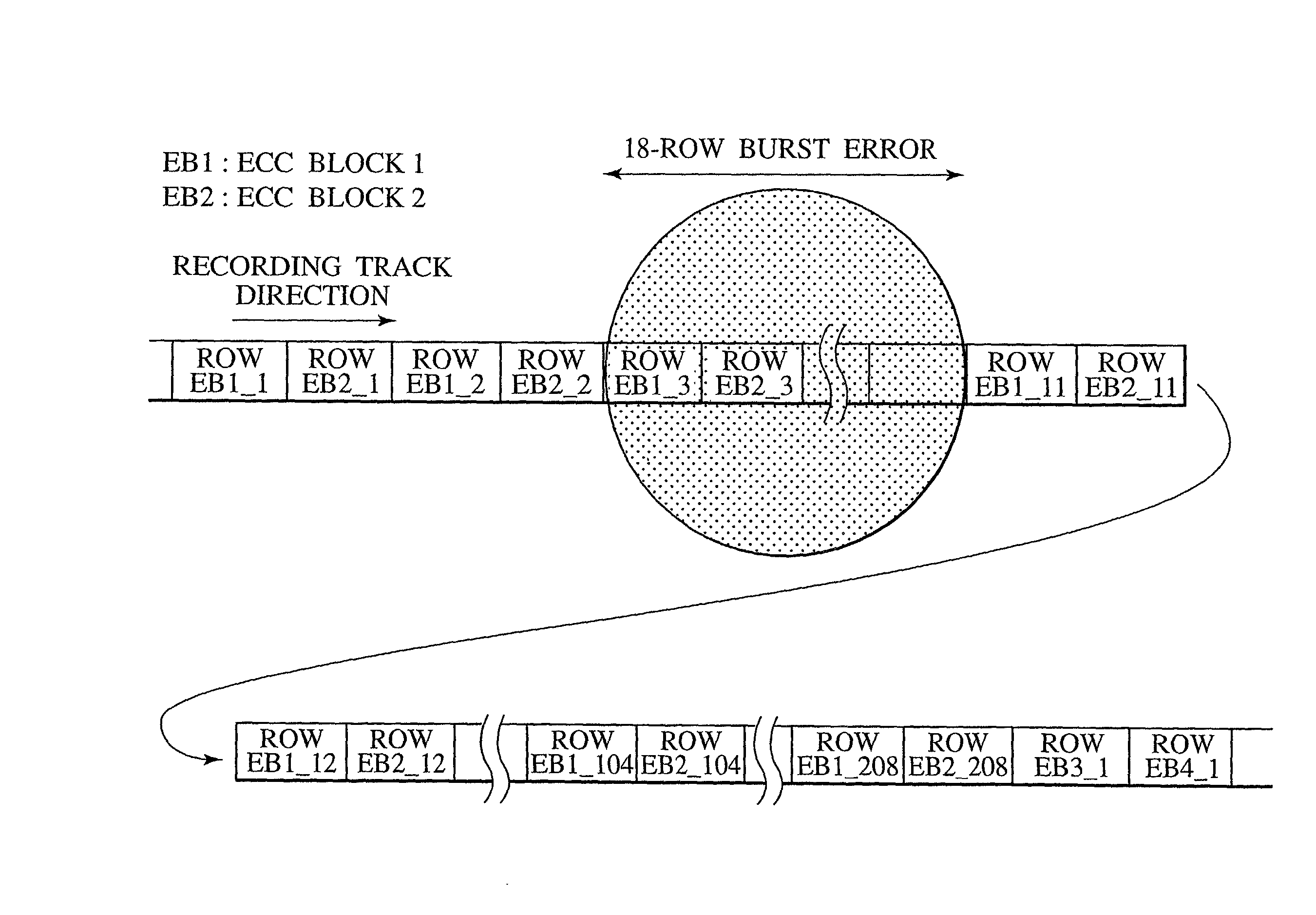
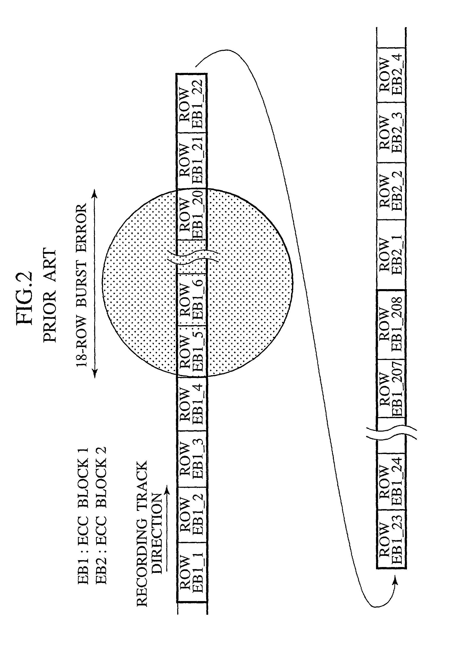
[0044] FIG. 3 shows the layout of data on a data recording medium in a first embodiment according to the present invention. In this embodiment, an interleave method is used in which data, which is error-correction-coded by the product coding method, is distributed on a recording medium. As shown in FIG. 3, with two consecutive product-coded ECC blocks, EB1 and EB2, as a set, the first row of the first ECC block EB1 is followed by the first row of the second ECC block EB2, which is followed by the second row of the first ECC block EB1, which is followed by the second row of the second ECC block EB2, and so on. That is, the rth row of the first ECC block is followed by the rth row of the second ECC block EB2. In this way, data is interleaved on a row basis.

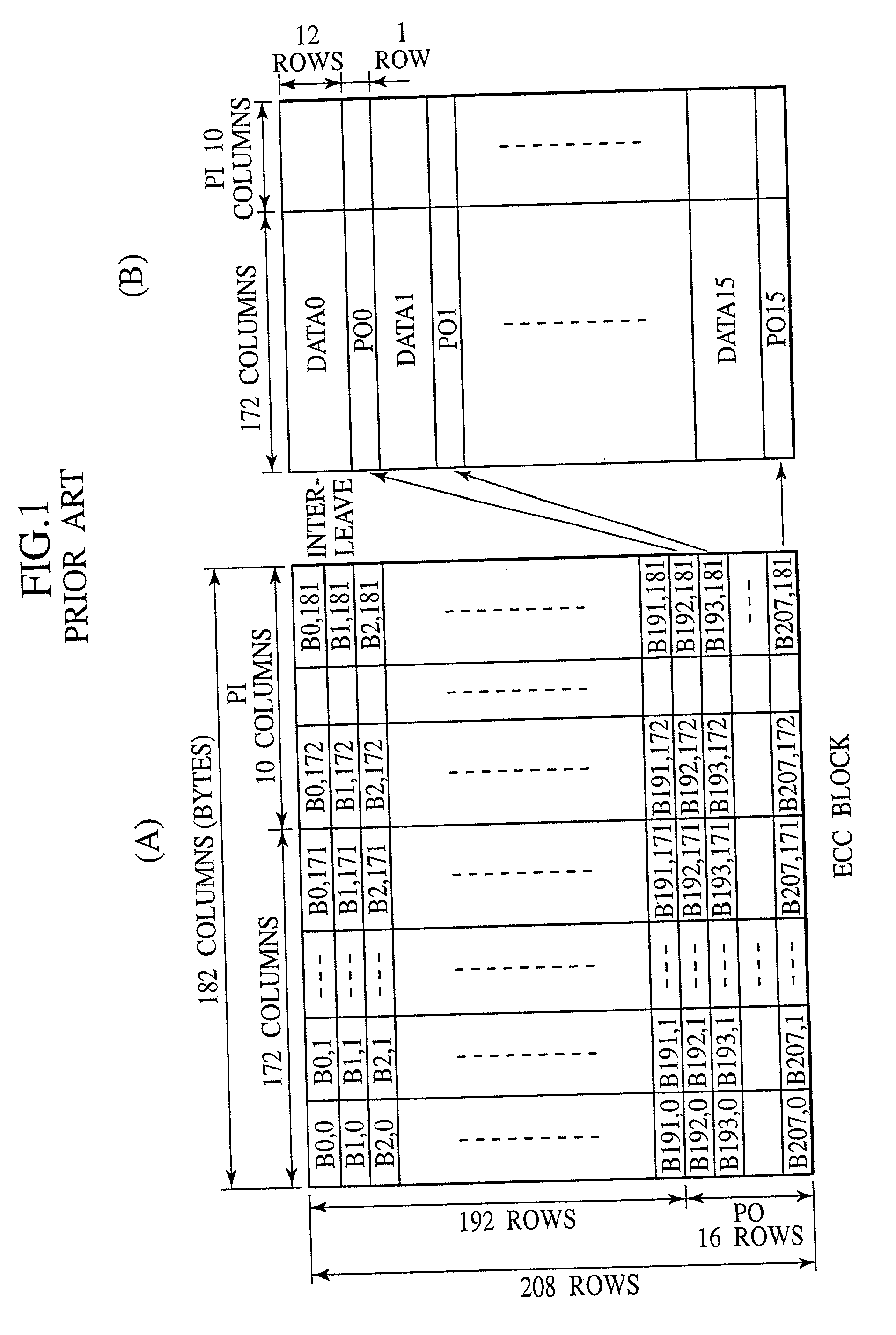
[0045] That is, in this embodiment, data in two ECC blocks, EB1 and EB2, are alternated on a row basis. The two ECC blocks, EB1 and EB2, are each configured as a product code block shown in FIG. 1. In addition, like a DVD, one PO pa...

second embodiment

[0107] Assume that a relatively short burst error has occurred in three positions when an optical disk is reproduced in the The errors are an eight-byte error at a position indicated by 61, a five-byte error at a position indicated by 62, and a 10-byte error at a position indicated by 63, respectively, in FIG. 13.

[0108] FIG. 14 shows the error distribution of de-interleaved data at reproduction time. If data bytes were not replaced on a byte basis at recording time, the errors would remain in the rows. On the other hand, in this embodiment, burst errors are distributed between two ECC blocks. The first ECC block EB1 includes four bytes of error, two bytes of error, and five bytes of error, while the second ECC block includes four bytes of error, three bytes of error, and five bytes of error, respectively. If the number of bytes of an error is odd as in the five-byte burst error in the 20th row, the number of error in one ECC block is one byte longer than that of the corresponding e...


PUM


Abstract

With two consecutive product-coded ECC blocks, EB1 and EB2, as a set, the rth row of first ECB block EB1 is followed by the rth row of second ECC block EB2 in such a way that the first row of first ECC block EB1 is followed by the first row of second ECB block EB2, which is followed by the second row of first ECC block ECB1, which is followed by the second row of second ECC block EB2, and so on, to interleave data on a row basis. That is, data of two ECC blocks, EB1 and EB2, is allocated alternately on a row basis. This allocation method allows an error to be distributed after reproduction even when a serious burst error extending 18 rows occurs in an ECC block.

Description

BACKGROUND OF THE INVENTION[0001] 1. Field of the Invention[0002] The present invention relates to a digital signal processing method, a data recording and reproducing apparatus, and a data recording medium, and more particularly to a digital signal processing method, a data recording and reproducing apparatus, and a data recording medium that are suitable for signal processing on a high-density recording medium.[0003] 2. Description of the Related Art[0004] Recently, data recording media have become denser. For example, as compared with a CD (Compact Disk), a DVD (Digital Versatile Disk) has a shorter minimum mark length and a higher track density with the track pitch of 0.74 .mu.m that is shorter than half of that of a CD. The user recording capacity of a single-sided, single-layer DVD is 4.7 GB.[0005] As a replacement of a disk in the current generation in which ared laser beam is used, manufacturers are now studying a next-generation super high-density optical disk that uses a v...

Claims


Application Information

Patent Timeline
IPC IPC(8): G11B7/00G11B20/12G06F11/10G11B20/18G11C29/00H03M13/11H03M13/27H03M13/29
CPCG11B20/1803G11B20/1833G11B20/1866G11B2020/1222G11B2020/1836G11B2020/1853G11B2220/2537H03M13/27H03M13/2909
Inventor IWATA, KAZUMIHAYAMI, ATSUSHI
Owner JVC KENWOOD CORP A CORP OF JAPAN
Why Eureka
Try Eureka