
Message transfer system

Inactive Publication Date: 2002-04-04
APPLE INC
View PDF0 Cites 34 Cited by
  • Summary
  • Abstract
  • Description
  • Claims
  • Application Information

AI Technical Summary

Benefits of technology

[0016] Preferably greetings associated with the called parties of the remote messaging system are stored by the local messaging system, and the method includes the step of, responsive to the instructing step, playing a greeting to at the local messaging system. This has an advantage of minimising the time that the call across the network needs to be held.
[0046] The call between the calling entity and the called entity can be initiated via the public switched telephone network. The advantage of using these methods and apparatus with such a call is that the time occupied by the calling party on an expensive voice telephone line is reduced to a minimum and in some cases there can be no charge for the voice part of the message transfer. Rather than using the expensive resources of the switched network, a data network is used instead. Further, by using a data path for processing a voice mail message, data compression can be used so that the message can be passed over the data path using a minimum time and consequently reducing the cost to a minimum.
[0047] The methods and apparatus according to the invention also have advantages where the call between the calling entity and called entity is via a data network, such as the internet, as would be the case where the calling entity and called entity are communicating using voice over internet techniques. By recording a message at a messaging system local to the calling entity, digital signal processing (DSP) resources of the gateways are freed for use with real-time calls. There is a further advantage that the quality of the recorded message and of voice prompts and greetings during the voice messaging session are improved because the session takes place local to the calling party.

Problems solved by technology

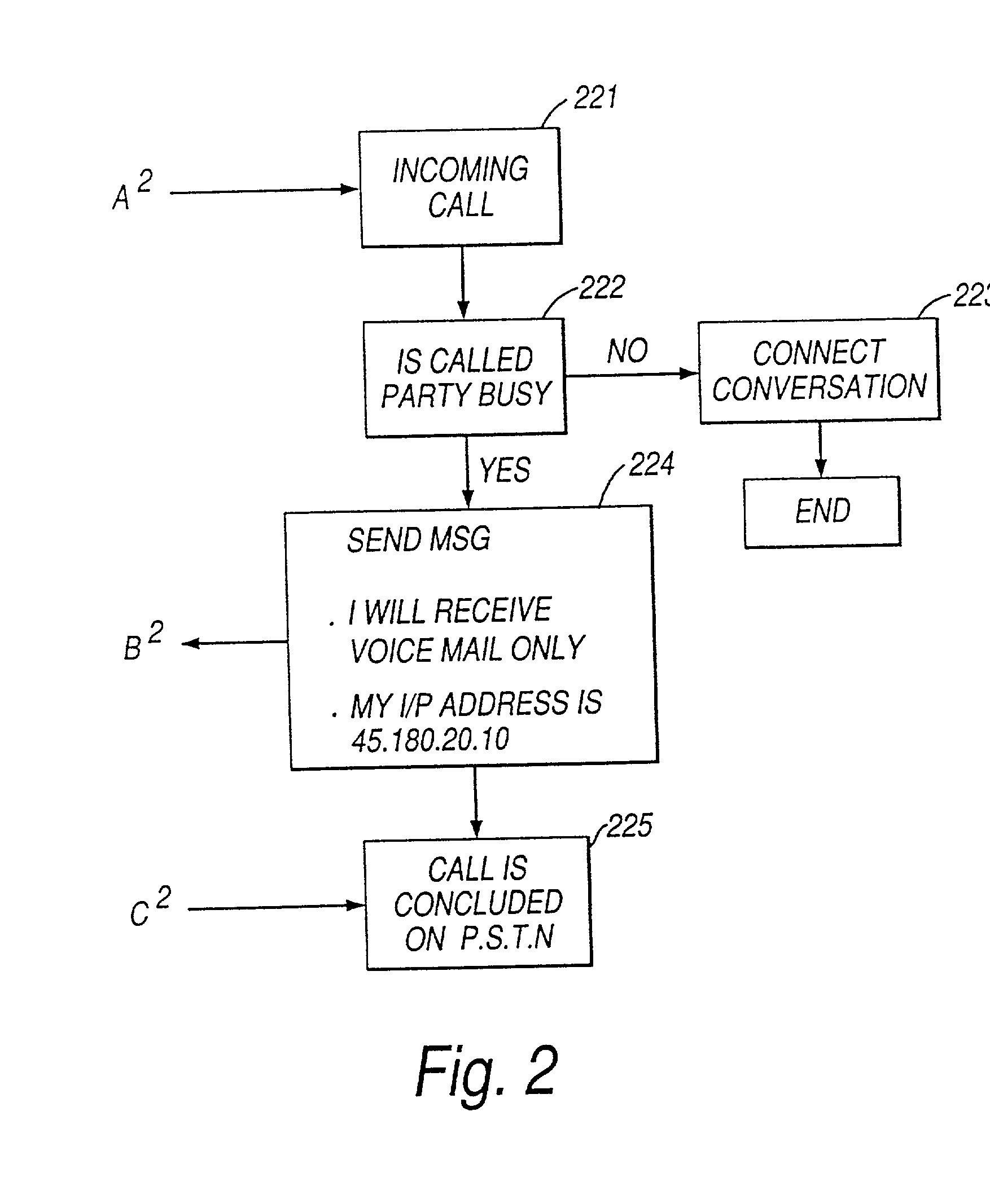
An unsuccessful attempt to reach to the remote party in person results in the local voice mail system performing voice mail tasks locally rather than at the remote voice mail system.

Method used


Image

  • Message transfer system
  • Message transfer system
  • Message transfer system

Examples


Embodiment Construction

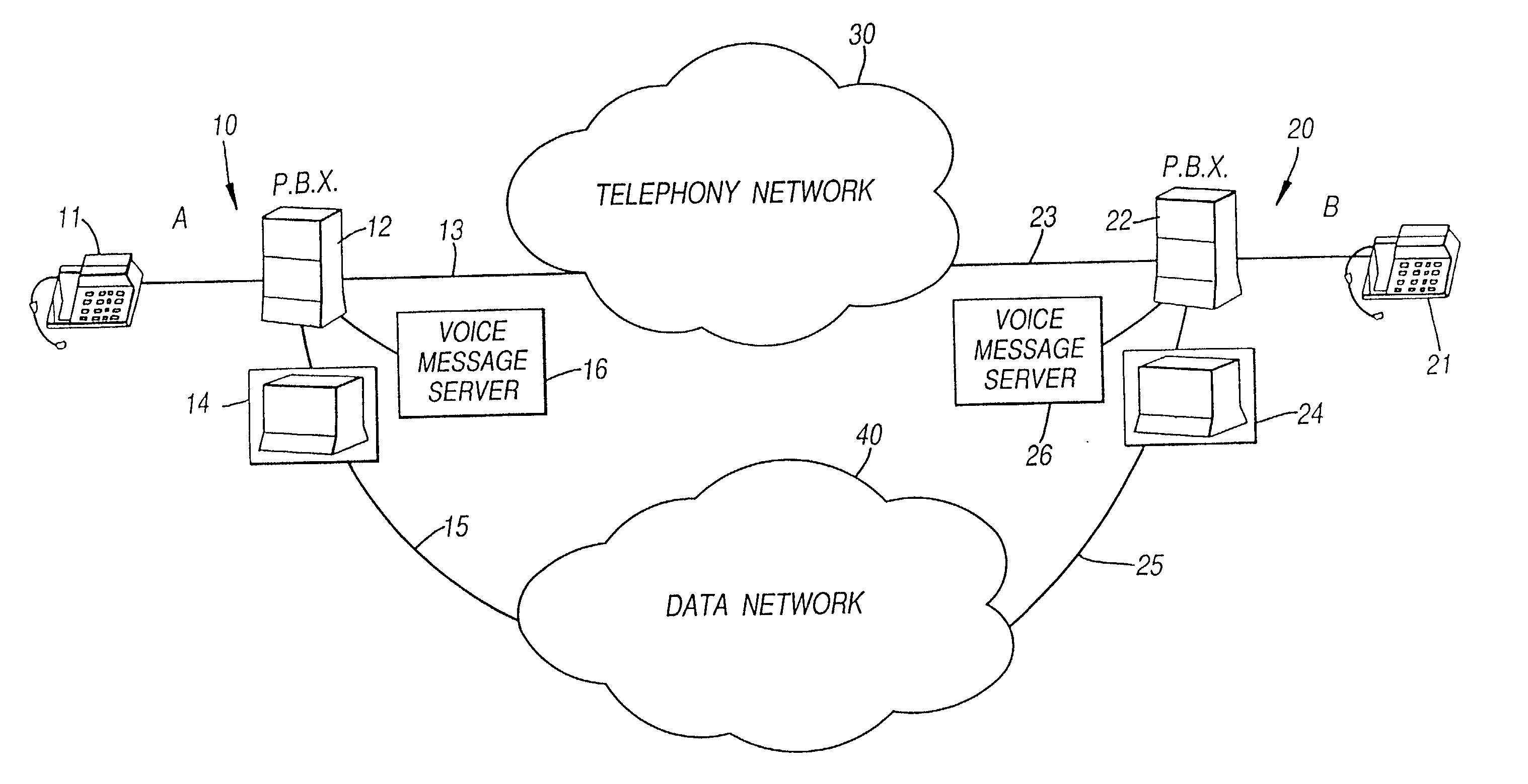
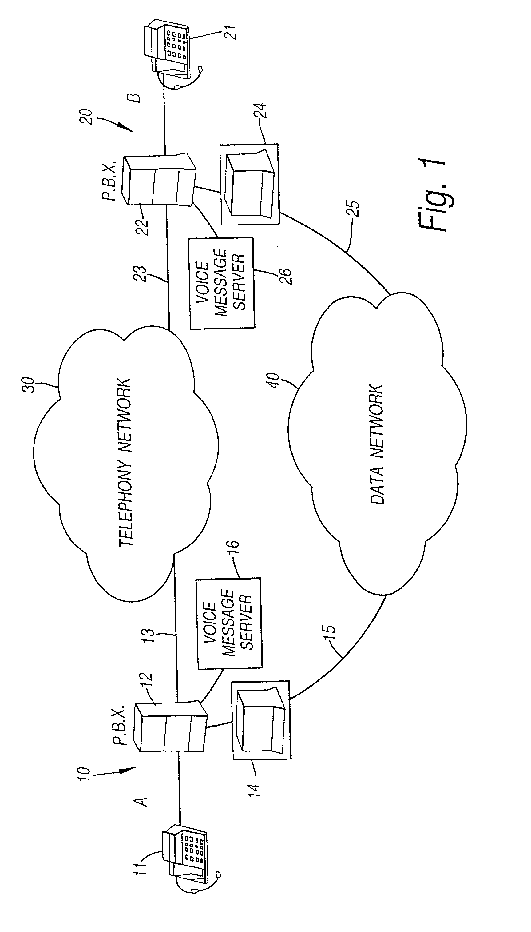
[0064] Referring now to FIG. 1, this shows in diagrammatic form a message transfer system between a calling entity (10) and a called entity (20). The calling entity comprises a telephone set 11 connected to a switching system such as a digital PBX (12) which has access to a voice network 30 via a conventional voice channel or line (13). The switching system (12) is also connected to a data network access device 14 which is connected by a separate data channel or line (15) to a data network (40). The called entity has similar equipment namely a telephone set (21), a switching system (22) connected to the telephone network (30) via a normal voice channel or line (23), and a data network access device (24) connected to the data network (40) via a data channel or line (25).

[0065] Modern digital switching systems usually have provisions for handling voice mail i.e. messages for persons who have been unable to answer a telephone call. A voice mail server (16) is consequently shown connect...


PUM


Abstract

An apparatus and method for transferring a message from a calling party to an unavailable telephonically called party. The method comprises the steps of inititating a call to the called party over a communications channel, identifying that the called party is not available and instructing the calling entity to record the message at the calling entity and after recording to transmit the message to the called entity as a data message via a data channel for reception by the called entity. The system reduces the use of the voice / telephone communications networks by allowing a voice message to be transmitted through data channels, reducing the amount of voice traffic on the voice communication lines. The fact that the original voice message was actually stored with the calling entity after the telephone voice communication had been discontinued is transparent to both the calling party and the called party. Greetings for the called party can be stored at a messaging system of the calling entity.

Description

[0001] This application is a continuation-in-part of application Ser. No. 08 / 959,579, filed Nov. 3, 1997.[0002] The present invention relates to a method and apparatus for transferring messages between two remote parties. In particular, it relates to voice mail systems and in a preferred form, to a method of, in the event of a busy or no-answer condition, playing a greeting and recording a message locally then forwarding that message to the remote voice mail system of the called party via a data network.[0003] Many telephone calls today do not achieve their intended objective of putting two parties into direct voice communication with each other. Usually, the calling party ends up leaving a voice message which is subsequently listened to by the called party. Voice mail systems serve the primary function of recording a message when the party for whom a call is intended does not answer the call in person.[0004] In the event of an incoming call at a telephone switch of a system equippe...

Claims


Application Information

Patent Timeline
IPC IPC(8): H04M3/533H04M3/537H04M7/00H04M7/12
CPCH04M3/53308H04M3/53325H04M3/53383Y10S379/908H04M7/0009H04M7/009H04M7/12H04M3/537H04M7/0033H04M7/0057
Inventor O'DONOVAN, JOHN JOSEPHWILLLIAMS, JEFFCRUICKSHANK, BRIANFLORENCE, LLOYD
Owner APPLE INC
Learn More