Eureka AIR delivers breakthrough ideas for toughest innovation challenges, trusted by R&D personnel around the world.

Use of OPA for switching and routing in WDM networks

Inactive Publication Date: 2002-04-25
TELEFON AB LM ERICSSON (PUBL)
View PDF6 Cites 5 Cited by
  • Summary
  • Abstract
  • Description
  • Claims
  • Application Information

AI Technical Summary

Benefits of technology

[0012] The object of the invention is to combine several functions into one arrangement to provide an efficient transmission of optical information in order to create network flexibility.
[0013] An advantage with the invention is the possible reception of a signal, free from chromatic dispersion, without having to compensate for chromatic dispersion along the path from a sending site to a receiving site.
[0014] Another advantage is the reception of a fully amplified signal without having to use amplifiers along the path from a sending site to a receiving site.
[0015] Yet another advantage is the possibility to use the two sets of wavelengths carrying the same information, as redundancy, and thereby appropriate safety to the system.
[0016] Yet another advantage is the possibility to contrary to traditional transponders do all the processing of wavelength conversion in the optical domain only.
[0017] Yet another advantage is that the protection link in the case of redundancy, after e.g. a fiber break accidentally can be longer than the main transmission fiber line. The amplification and dispersion compensation features of the idler channels at the conjugate wavelengths can then be very useful to achieve the desired performance without additional amplifiers and dispersion compensation elements.

Problems solved by technology

It leads to additional receiver penalty due to temporal spreading of optical signals travelling through optical fibers.

Method used


Image

  • Use of OPA for switching and routing in WDM networks
  • Use of OPA for switching and routing in WDM networks
  • Use of OPA for switching and routing in WDM networks

Examples


second embodiment

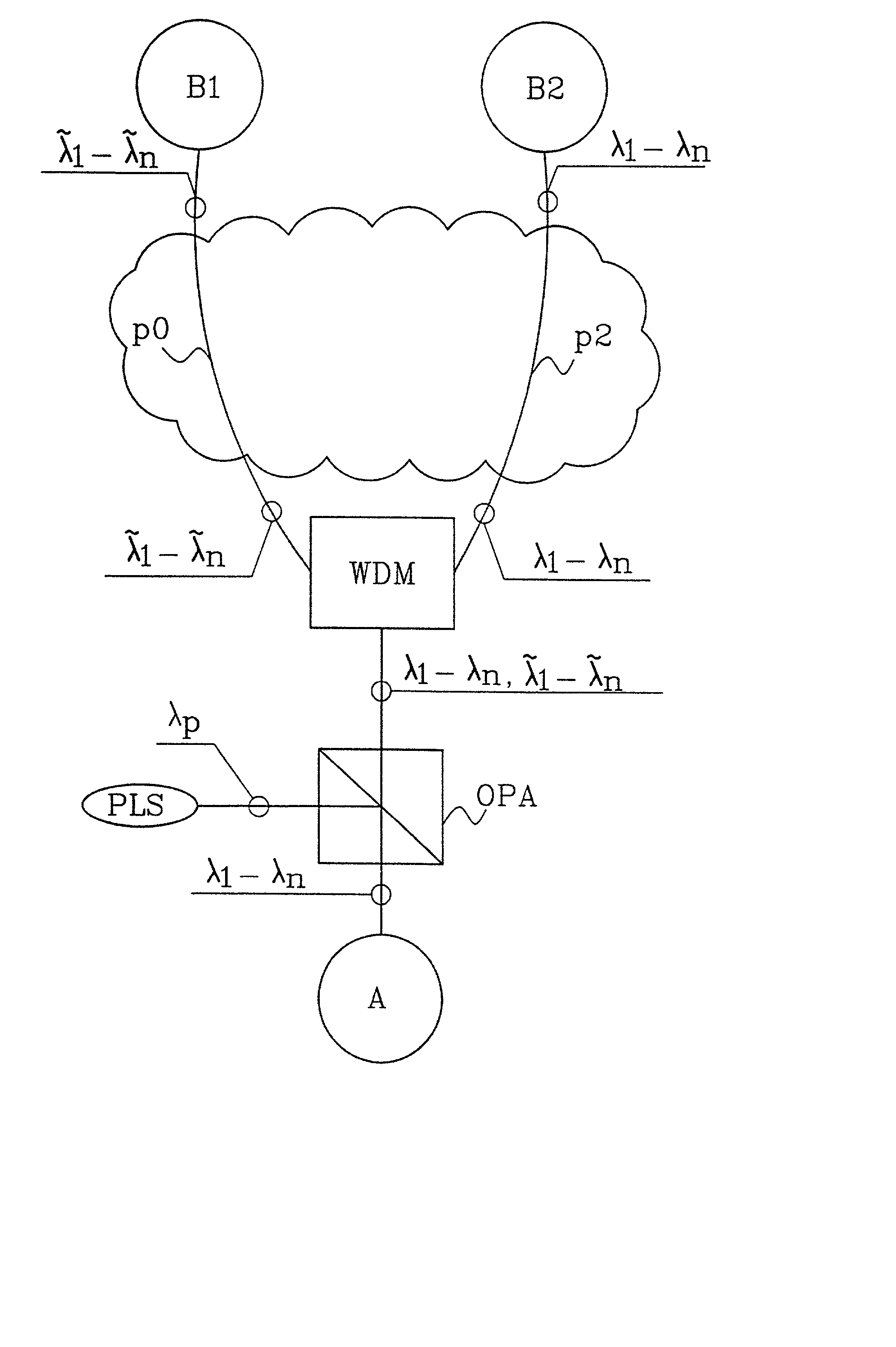
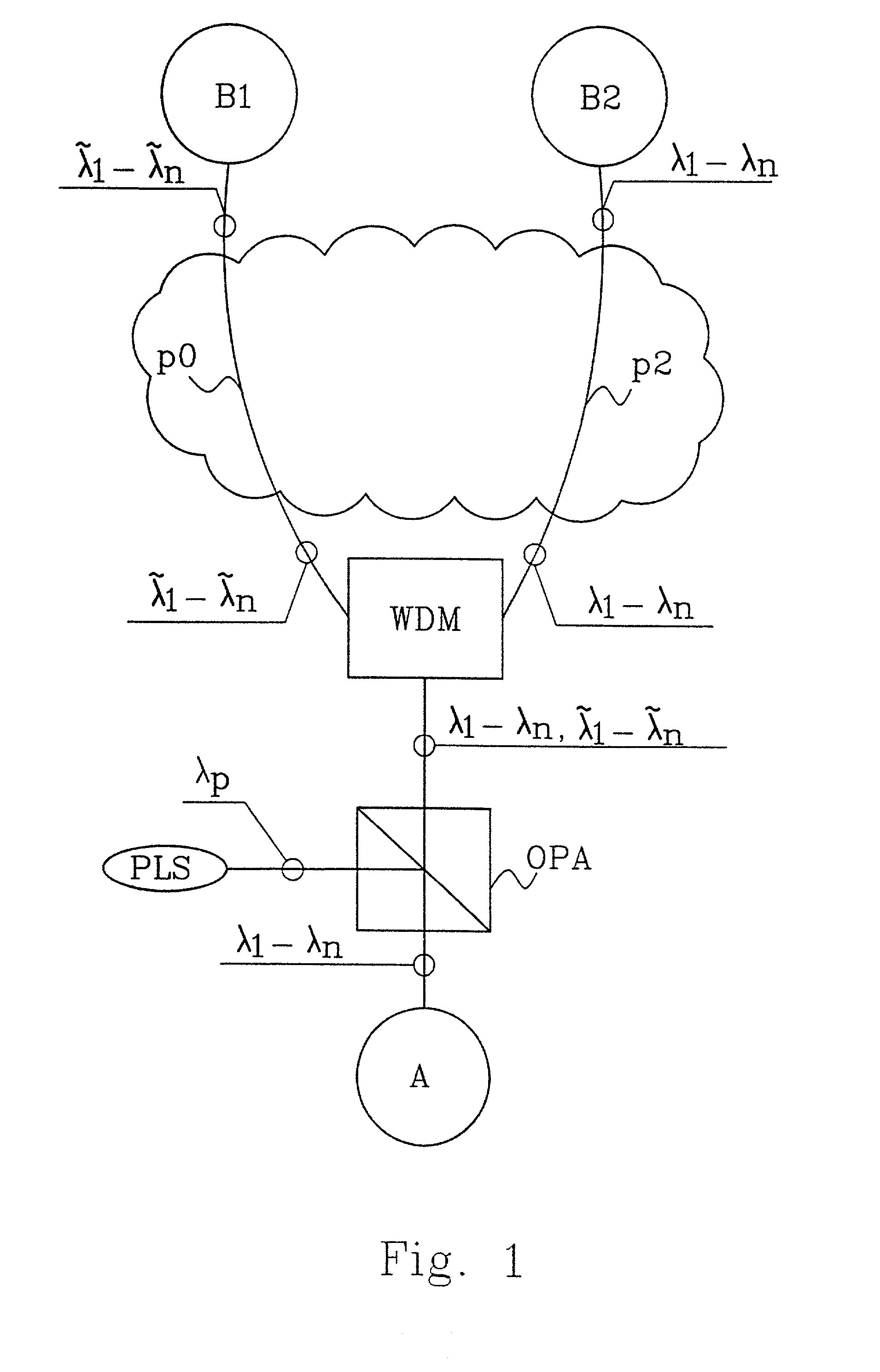
[0035] A method according to the invention will now be analyzed and described. The method will be explained by using the references that already have been mentioned in FIGS. 1 and 2. The most essential steps of the method are disclosed with a flow chart in FIG. 4. The method below will disclose how the sending site A transfer optical information at a set of conjugate copy wavelength to the first receiving site B1. The same optical information is also transferred at a set of input wavelengths to a second receiving site B2. The purpose of this type of transfer will then be explained. The method includes the following steps:

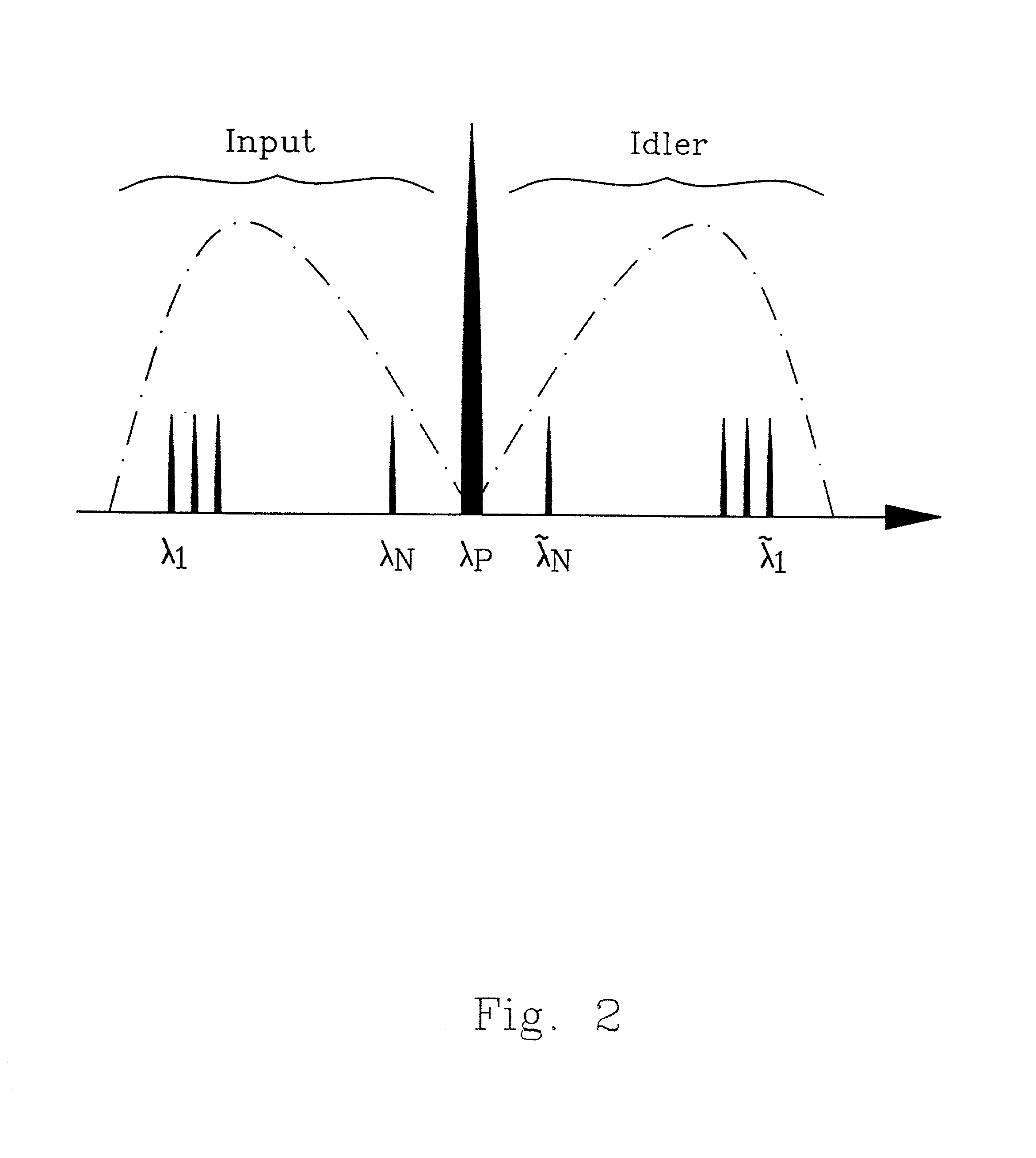
[0036] The sending site A sends optical information in channels, on a set of input wavelength .lambda..sub.1 .lambda..sub.n to the optical parametric amplifier OPA. Each channel is transferred at one input wavelength. In FIG. 4 this is disclosed with a block 201.

[0037] In the optical parametric amplifier OPA, the input wavelengths .lambda..sub.1.div..lambda..sub.n a...

third embodiment

[0044] A method according to the invention will now be analyzed and described. The method will be explained by using the references already mentioned in FIG. 5. The most essential steps of the method are disclosed with a flow chart in FIG. 6. The method below will disclose how the sending site A transfer optical information at a set of conjugate copy wavelength to the receiving site B3. At the beginning of the procedure the optical parametric amplifier OPA is deactivated and information is transferred transparent through the optical parametric amplifier OPA at the input wavelengths .lambda..sub.1.div..lambda..sub.n from site A on the path P1 to the receiving site B3. After a path error the optical amplifier OPA is activated and the information is instead transferred at the conjugate copy wavelengths {tilde over (.lambda.)}.sub.1.div.{tilde over (.lambda.)}.sub.n. The error in the path is shown with an X-symbol on the path p1. The method according to the invention includes the follow...


PUM


Abstract

The present invention is an arrangement for utilizing optical information sent through an optical network from a sending site A to a at least one receiving site B1, B2, B3. The arrangement comprises an optical parametric amplifier OPA for receiving the optical information sent at a set of input wavelengths lambd1÷lambdn. The arrangement also comprises a mixer in the amplifier OPA for mixing the input wavelengths lambd1÷lambdn, with an optical pump wavelength lambdp and means for generating a set of optical conjugate copy wavelengths {tilde over (lambd)}1÷{tilde over (lambd)}n extracted from the set of input wavelengths lambd1÷lambdn. A WDM-splitter is used for separating the set of input wavelengths lambd1÷lambdn from the set of conjugate copy wavelengths {tilde over (lambd)}1÷{tilde over (lambd)}n. Fibers are used for forwarding the set of input wavelength and / or the set of conjugate copy wavelengths {tilde over (lambd)}1÷{tilde over (lambd)}n individually to the at least one of the receiving site B1, B2, B3.

Description

[0001] The present invention relates to a method and an arrangement to provide efficient transmission of optical information in an optical transmission system.DESCRIPTION OF RELATED ART[0002] Optical transmission systems utilizing optical fibers as the optical signal transmission medium are gaining in popularity. This is especially because their substantial immunity to interference or external influences and their ability to transmit a great number of communications channels in the same physical medium--the optical fiber, without cross talk between the channels.[0003] Modern optical networks contain a number of different optical devices to manipulate information in the form of optical signals transmitted through a network of optical fiber links. The main principles of design of optical networks require versatile processing of optical signals to provide necessary network flexibility. Such a processing assumes channel routing, add / drop and switching functions, conversion of optical si...

Claims


Application Information

Patent Timeline
IPC IPC(8): H01S3/108H04B10/17H04J14/02
CPCH01S3/1083H04B10/2939H04J14/0227H04J14/0241H04J14/0282H04J14/0294H04J14/0279
Inventor POPOV, SERGEIVANIN, EVGENY
Owner TELEFON AB LM ERICSSON (PUBL)
Why Eureka
Eureka Blog
Learn More