Intrusion detection radar system

a radar system and intrusion detection technology, applied in the field of microwave doppler radar detection, to achieve the effect of reducing the nuisance alarm ra

a radar system and intrusion detection technology, applied in the field of microwave doppler radar detection, to achieve the effect of reducing the nuisance alarm ra

US20020060639A1Inactive Publication Date: 2002-05-23SOUTHWEST MICROWAVE

Image

  • Intrusion detection radar system
  • Intrusion detection radar system
  • Intrusion detection radar system

Examples


Embodiment Construction

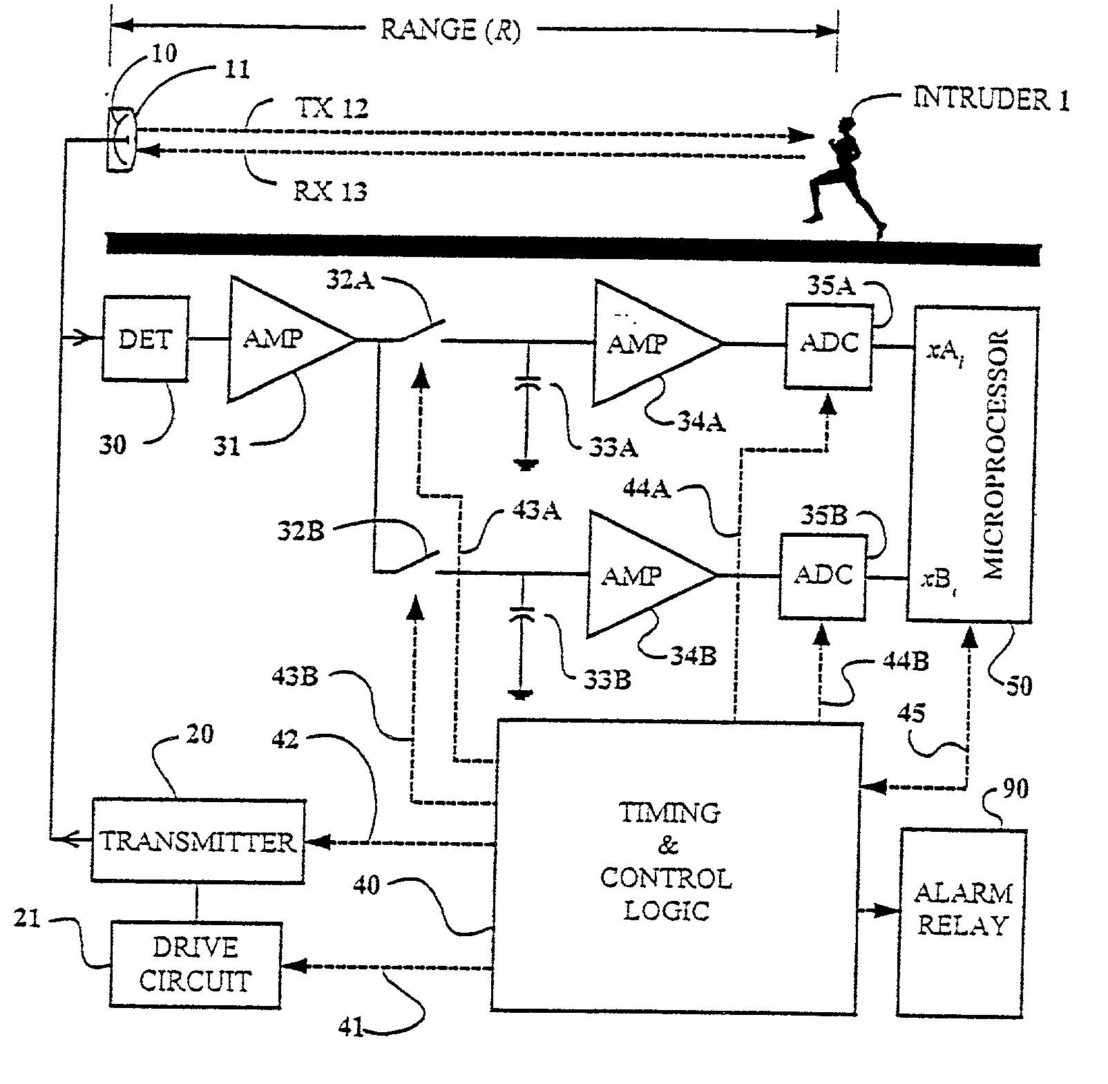
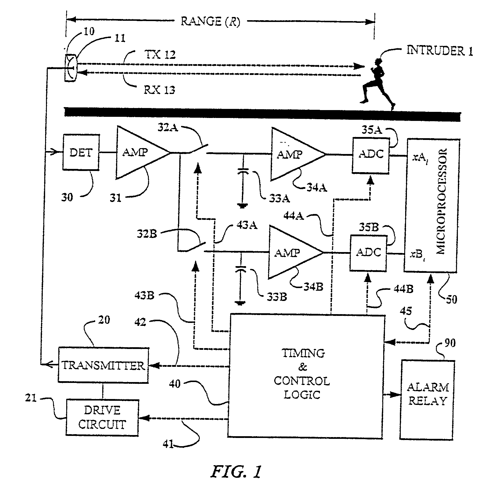
[0026] The basic operation of the Doppler intrusion sensor is illustrated in the upper portion of FIG. 1. A pulse of RF energy 12 is transmitted from antenna 10 and through radome 11. It propagates over the surface of the terrain to illuminate moving intruder 1. A small percentage of this RF pulse 13 is reflected back through radome 11 to antenna 10. It is this reflected signal that is used to detect the presence of the intruder.

[0027] Radome 11 is designed to protect the antenna from the elements while providing minimal RF attenuation. The radome is curved in such a way as to minimize the Doppler response due to rain droplets that form and roll down the surface of the radome. The distance from the antenna to the radome determines the minimum range to a water droplet.

[0028] The antenna field pattern associated with antenna 10 determines the shape of the detection zone. The horizontal beam width of the antenna creates a detection zone that increases approximately linearly with range....


PUM


Abstract

An outdoor microwave transceiver intrusion detector that alternately transmits pulses of RF energy at two different frequencies and uses range and direction of travel information derived from the phase of the two Doppler responses to optimize the signal processing and apply range dependent thresholds. The time delay between the onset of the transmitted pulse and the sample of the Doppler response is controlled to provide an accurate range cutoff. The two frequencies are selected so that the difference in phase of the Doppler response at the two frequencies increases from zero to ninety degrees as the target goes from the Transceiver to the maximum range. Digital signal processing is used to measure the difference in phase of the two Doppler responses and translate this information into location of the target. The location information is used to create a number of range bins. The response integration time and the threshold level are optimized for each of the range bins thereby minimizing the number of nuisance alarms.

Description

[0001] The present application is based on provisional patent application Serial No. 60 / 240,468 filed on Oct. 11, 2000.[0002] This invention relates to outdoor intrusion detection using microwave transmissions, and more particularly to a Doppler Radar sensor using two frequencies to derive range information, which is used to optimize the detection process to discriminate against nuisance alarms and detect human intruders.[0003] The detection of human intruders as they cross outdoor perimeters plays a significant role in the prevention of crime. Intrusion detection sensors based on Doppler Radar are in common use today. For example, the assignee produces a number of products based on U.S. Pat. No. 4,697,184 that are used at high security sites around the world.[0004] The major challenge in developing a Doppler Radar for intrusion detection is to detect human targets at ranges up to 400 feet while not detecting very small moving objects such as rain drops near the radar antenna or on ...

Claims


Application Information

Patent Timeline
23 May 2002
Publication
US20020060639A1
IPC
G01S13/56; G01S13/58; G01S13/62
CPC
G01S13/56; G01S13/62; G01S13/582
Inventors
HARMAN, ROBERT KEITH