Friction clutch

a clutch and friction technology, applied in the field of friction clutches, can solve the problems of complex multi-stage process, limited cooling air supply to the interior of the clutch, and clutch overheating,

Inactive Publication Date: 2002-06-13
ZF FRIEDRICHSHAFEN AG
View PDF0 Cites 8 Cited by
  • Summary
  • Abstract
  • Description
  • Claims
  • Application Information

AI Technical Summary

Problems solved by technology

In a friction clutch of this type, there is the problem that the supply of cooling air to the interior of the clutch is limited.
This means that the clutch can overheat at least wh...

Method used


Image

  • Friction clutch
  • Friction clutch
  • Friction clutch

Examples


Embodiment Construction

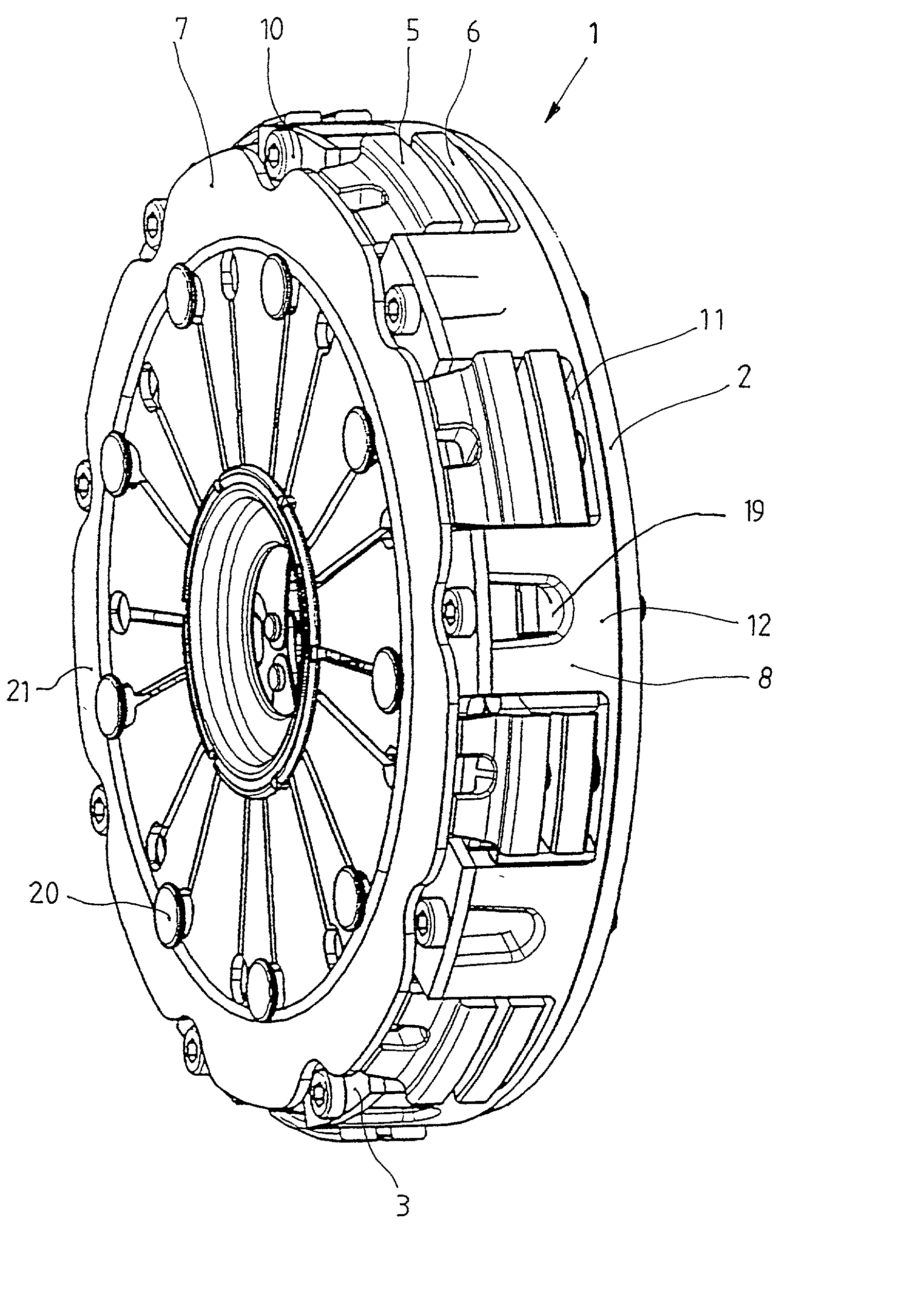
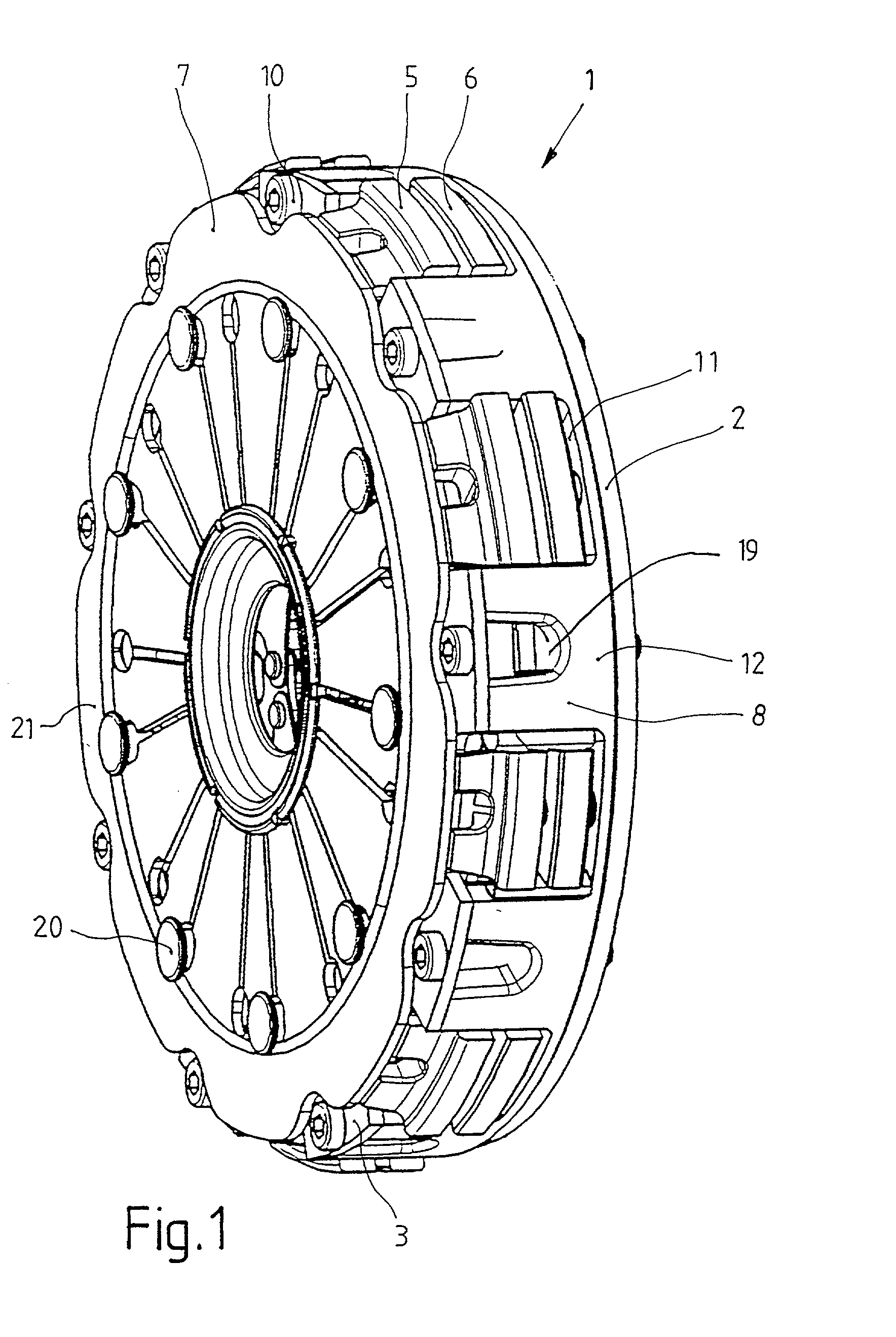
[0025] The friction clutch 1 shown in perspective in FIG. 1 consists primarily of an input part 2, which is flanged to the crankshaft of an internal combustion engine; a housing 3, which is attached to the end surface of the input part; and a stored energy element in the form of diaphragm spring 21, which is supported against the axial side of the housing by spacer bolts 20 so that the spring is free to move back and forth. This diaphragm spring 21 acts on knife edges formed on the pressure plate 5 and thus presses the plate in the engaged state against the clutch disk. With respect to its design and function, the friction clutch 1 shown here corresponds for the most part to the friction clutch described in U.S. application Ser. No. 09 / 602,804, the content of which is incorporated herein by reference.

[0026] The housing 3 shown in FIG. 3 is connected to the input part 2 by fastening means, which are designed here as screws 10. These screws pass through attachment holes in the radiall...


PUM


Abstract

Friction clutch for use in the drive train of a motor vehicle with an input part, a clutch housing, at least one clutch disk in working connection with a takeoff element, and a pressure plate working together with the input part, the force of a stored-energy element acting on the pressure plate to transmit torque to the clutch disk. The radially outer area of the input part has axially oriented walls extending along at least part of the circumference to cooperate with the pressure plate.

Description

[0001] 1. Field of the Invention[0002] The present invention pertains to a friction clutch for use in the drive train of a motor vehicle with an input part, a clutch housing, at least one clutch disk in working connection with a takeoff element, and a pressure plate working together with the input part, the force of a stored-energy device acting on the pressure plate to transmit torque to the clutch disk.[0003] 2. Description of the Related Art[0004] U.S. Pat. No. 5,779,018 discloses a multi-disk friction clutch in which the several clutch disks are designed in the form of a set of plates connected to a common hub part. In the clutch housing, a pressure plate is provided, which can be acted upon by a stored-energy device, and in addition several intermediate disks are connected nonrotatably to the clutch housing, these intermediate disks engaging between the plates. By means of the stored-energy device, the intermediate disks and the plates can be pressed against each other to gener...

Claims


Application Information

Patent Timeline
IPC IPC(8): F16D13/70F16D13/72
CPCF16D13/72F16D13/70
Inventor VOGT, SEBASTIAN
Owner ZF FRIEDRICHSHAFEN AG
Why Eureka
Try Eureka