Lamp ignition with automatic compensation for parasitic capacitance

Inactive Publication Date: 2002-06-13
KONINKLIJKE PHILIPS ELECTRONICS NV
View PDF0 Cites 0 Cited by
  • Summary
  • Abstract
  • Description
  • Claims
  • Application Information

AI Technical Summary

Benefits of technology

0010] Collectively, the energy source and the voltage clamping device are capable of maintaining the peak ignition pulse voltage at a substantially constant value over a predetermined range of parasitic loading capacitance values.

Problems solved by technology

Designing igniter circuitry which effectively compensates for such parasitic capacitances is difficult, because it varies significantly with, for example, the length of wiring that is used to

Method used


Image

  • Lamp ignition with automatic compensation for parasitic capacitance
  • Lamp ignition with automatic compensation for parasitic capacitance
  • Lamp ignition with automatic compensation for parasitic capacitance

Examples


Embodiment Construction

)

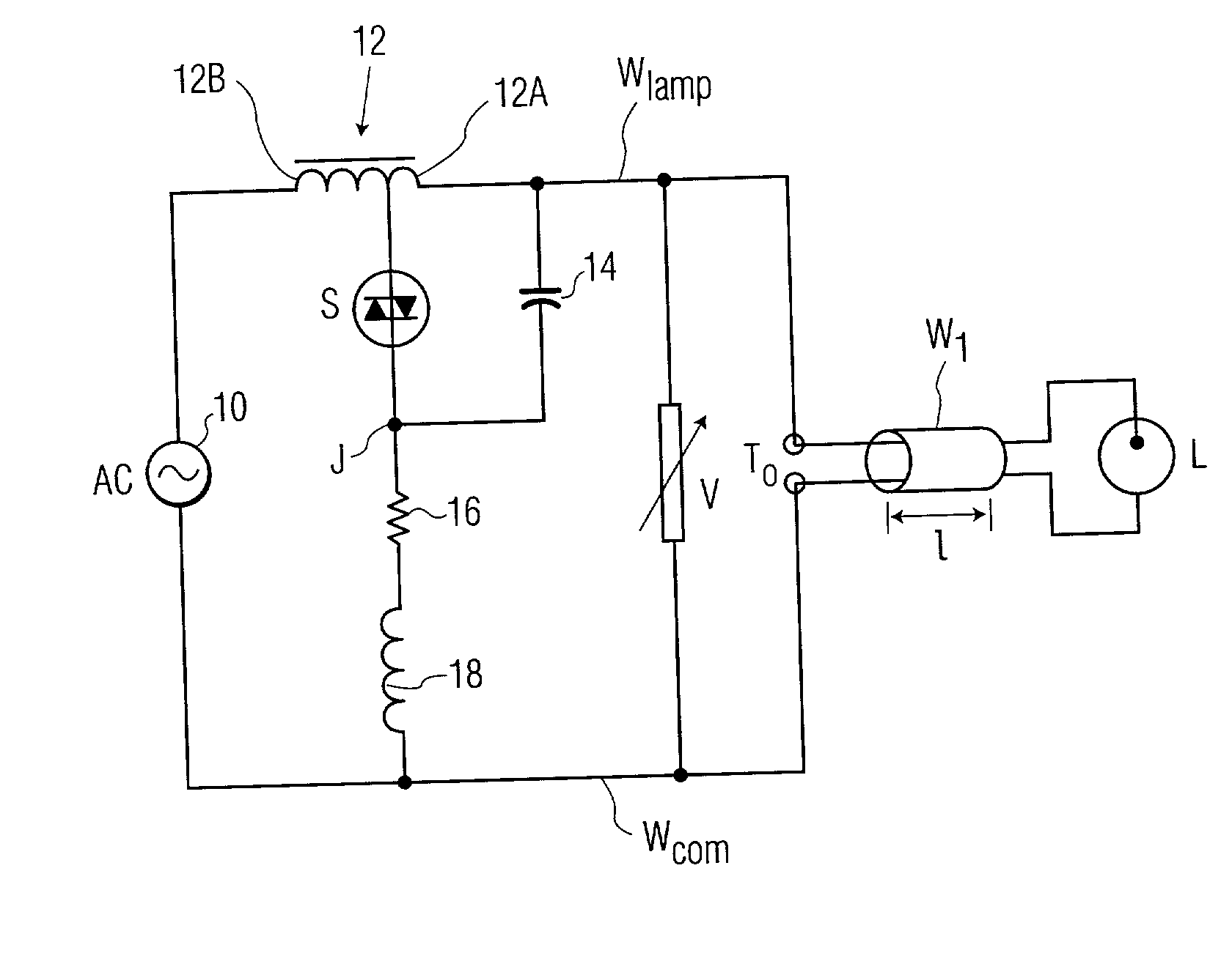
[0015] FIG. 1 illustrates an exemplary embodiment of an electro-magnetic ballast which incorporates the invention. This ballast includes an AC source 10 and an autotransformer 12 electrically connected in a first series loop with a gaseous discharge lamp L via a lamp supply conductor W.sub.lamp, a common conductor W.sub.com, and a length of two-conductor cable W.sub.l extending from output terminals T.sub.o of the ballast to the lamp L. The autotransformer is formed from a ballast inductor having a primary winding 12A and a secondary winding 12B. A bidirectional voltage-sensitive switch S is electrically connected in a second series loop with a capacitor 14 and the primary winding 12A. In this embodiment the switch S is a sidac. A resistor 16 and an RF blocking coil 18 are electrically connected in series between a junction J (connecting one side of the sidac S and the capacitor 14) and the common conductor W.sub.com. A varistor V is electrically connected between the lamp supply c...


PUM


Abstract

Ballast circuitry is provided for powering a gaseous discharge lamp which has a range of possible parasitic loading capacitances associated with it. The circuitry includes a reactive source of ignition pulses which stores sufficient energy to charge the highest value of parasitic loading capacitance in the range to at least the minimum ignition voltage of the lamp. A voltage clamping element limits the peak voltage of the ignition pulses, even at the lowest value of parasitic loading capacitance in the range, to a maximum permissible voltage that may be applied to the lamp. The reactive source and the voltage clamping element cooperate to automatically provide high-energy ignition pulses to the lamp, with peak voltages well within permissible limits, over the entire range of parasitic loading capacitances.

Description

[0001] BACKGROUND OF THE INVENTION[0002] 1. Field of the Invention[0003] This invention relates to gaseous discharge lamps which ignite at voltages that are much higher than their operating voltages and, in particular, to the igniting of such lamps.[0004] 2. Description of Related Art[0005] Common characteristics of a gaseous discharge lamp are its negative resistance and high igniting voltage. Circuitry for powering such a lamp typically includes a current limiting means, such as a ballast, to compensate for the negative resistance, and often includes igniter circuitry for generating high-voltage pulses to ignite the lamps. Such igniter circuitry commonly includes a voltage-sensitive switch (e.g. a sidac) for effecting the continual production of the high-voltage pulses until the lamp ignites. Upon ignition, the voltage across the lamp decreases from a higher open-circuit voltage (OCV) to a lower voltage, which causes the switch to change to a non-conducting state and to effect ter...

Claims


Application Information

Patent Timeline
IPC IPC(8): H05B41/18H05B41/04H05B41/292
CPCH05B41/042Y10S315/05H05B41/2928H05B41/00
Inventor DELIA, VINCENT JAMES
Owner KONINKLIJKE PHILIPS ELECTRONICS NV
Why Eureka
Try Eureka