Hybrid heat pump

a heat pump and hybrid technology, applied in the direction of heating types, domestic cooling devices, separation processes, etc., can solve the problems of affecting efficiency, overtaxing refrigerant cooled air coils, and insufficient humidity control of refrigerant air conditioner systems in humid environments

Inactive Publication Date: 2002-06-27
KORIN AMOS
View PDF0 Cites 48 Cited by
  • Summary
  • Abstract
  • Description
  • Claims
  • Application Information

AI Technical Summary

Problems solved by technology

For example, refrigeration air conditioner systems in humid environments are often inadequate with respect to acceptable humidity control, with or without refrigeration incorporated therein.
In wet or damp environments refrigeration air conditioner systems utilizing refrigerant cooled air coils are often overtaxed and their efficiency adversely affected.
A significant problem with heat pumps is that under certain circumstances an outdoor coil will, during a heating mode of operation, have frost accumulate thereon.
As the frost thickness increases, the overall efficiency of the system decreases dramatically, and energy is wasted.
This causes a serious waste of energy.
However, this also causes cooling of the controlled building which is in turn typically offset by a use of high cost, lower-efficiency, electric resistance heating.
Again, energy is wasted.
The accumulation of frost on evaporator coils of either a home or commercial refrigerator has been recognized as a problem for many years.
Such systems require complex valving for the refrigeration fluid and add some heat from the refrigeration fluid to the defrost coils.
Although such a system offers an improvement, it still consumes additional energy.
Desiccation is a process of removing vapor of one or more liquids out of a gas containing the vapor, resulting in vapor depleted or dry gas.
Using desiccant systems for removing moister from the processed gas or air is subject to several limitations.
This process requires an application of heat to the desiccant material and requires either alternating desiccation regeneration cycles or use of a mechanically cumbersome desiccant wheel.
Although membranes have been used in various separation applications, their use for heat pump systems has been limited.

Method used


Image

  • Hybrid heat pump
  • Hybrid heat pump
  • Hybrid heat pump

Examples


Embodiment Construction

[0060] The following description makes reference to the annexed drawings. All drawings illustrate exemplary embodiments of the present invention. Auxiliary equipment and conveying means, such as pumps, valves, heat exchangers, condensers, compressors, blowers, piping; ductwork, fittings and dampers either are not shown or are shown partially.

[0061] As used herein, the term "fluid" means a substances with no reference configuration of permanent significance, aggregate of matter in which molecules are able to flow past each other with out fracture planes forming. Subdivisions of fluids are gases vapors and liquids. The phrase "gaseous fluid" means a fluid where its volume is a function of pressure and its absolute temperature. All gaseous fluids approximately obey the ideal gas equation pv=nRT where p is pressure, v is volume, n is number of moles, R is the gas constant (0.082 liter atm / degK) and T is absolute temperature.

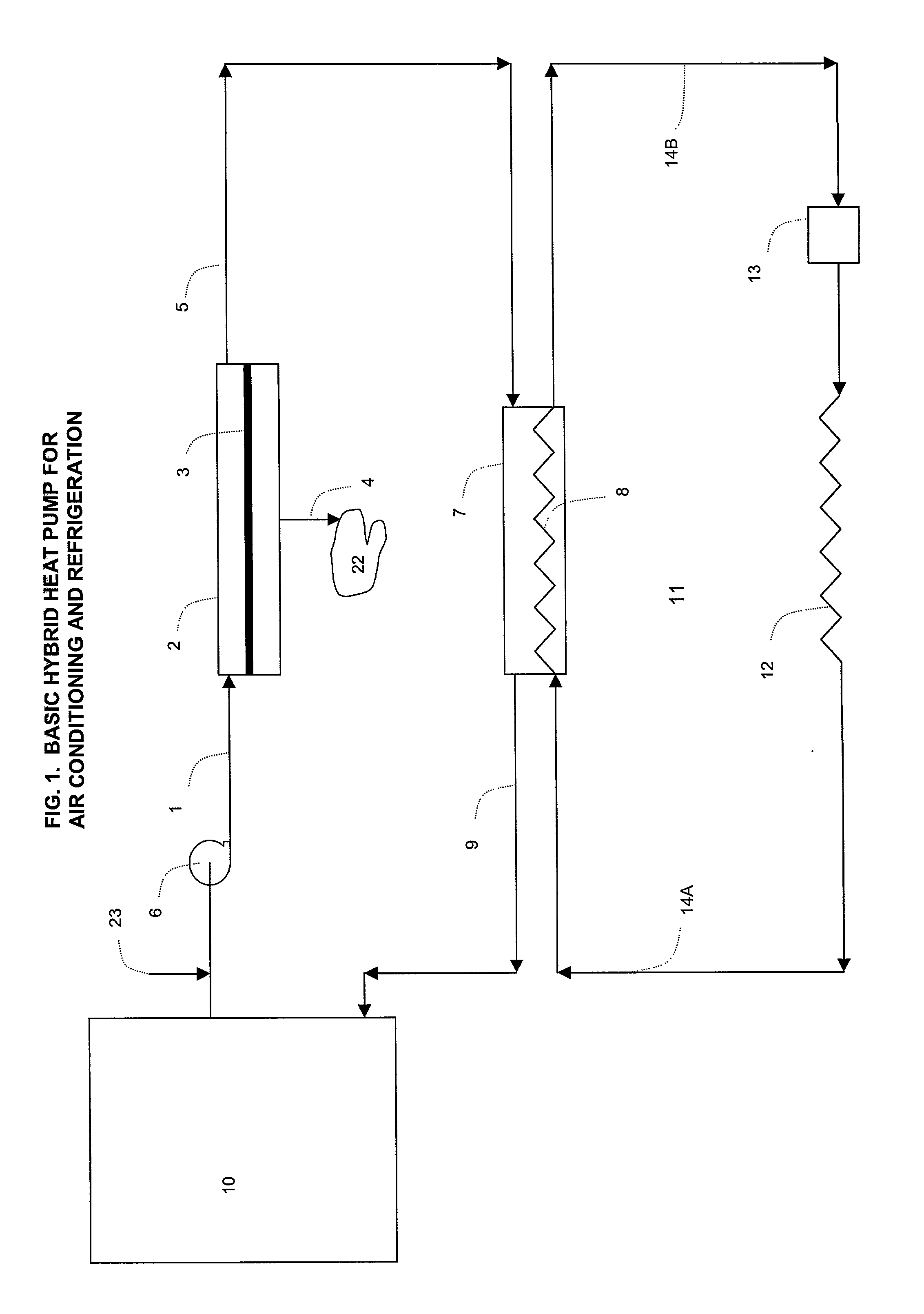
[0062] FIG. 1 shows a hybrid heat pump according to the present...


PUM


Abstract

There is provided a hybrid heat pump system. The system includes (i) a membrane permeator having a permselective membrane capable of selectively removing vapor from a vapor-containing gas to yield a dry gas, (ii) a heat pump having (a) an internal side for exchanging thermal energy with a process fluid, (b) an external side for exchanging thermal energy with an external environment, and (c) a thermodynamic mechanism for pumping thermal energy between the internal side and the external side in either direction, (iii) means for conveying the vapor-containing gas into the membrane permeator, and (iv) means for routing the dry gas to either of the internal side or the external side.

Description

[0001] The present application is claiming priority of U.S. Provisional Patent Application Seria No. 60 / 251,207, which was filed on Dec. 4, 2000, and U.S. Provisional Patent Application Serial No. 60 / 257,031, which was filed on Dec. 21, 2000.[0002] 1. Field of the Invention[0003] The present invention relates to a hybrid heat pump system and, more particularly, to a heat pump system that utilizes a combination of a conventional heat pump and a membrane permeator flow device for conditioning gas, preferably air, within an either enclosed or open space before the gas is treated by the heat pump.[0004] 2. Description of the Prior Art[0005] Humidity has an effect upon a building. As humidity increases, so does the presence of bacteria, mold and mildew. Therefore, having an ability to control humidity and lower its level will contribute to an elimination of microorganism propagating environments. For example, refrigeration air conditioner systems in humid environments are often inadequat...

Claims


Application Information

Patent Timeline
Patent Type & Authority Applications(United States)
IPC IPC(8): B01D53/22F24F3/14F24F5/00F25B29/00F25B30/00
CPCB01D53/22F24F3/14F24F5/0007F25B30/00F24F2003/144F25B29/00F24F2003/1435
Inventor KORIN, AMOS
Owner KORIN AMOS
Why Eureka
Try Eureka