

Ferromagnetic tunnel magnetoresistive devices and magnetic head
a magnetoresistive device and tunnel magnetoresistive technology, applied in the direction of maintaining head carrier alignment, magnetic bodies, instruments, etc., can solve the problems of the dependence on an applied bias voltage and the decrease in the tmr ratio, and achieve the effect of solving the dependence on the application of bias voltage and the decrease of the tmr ratio
- Summary
- Abstract
- Description
- Claims
- Application Information
AI Technical Summary
Benefits of technology
Problems solved by technology
Method used
Image

Examples
embodiment 2
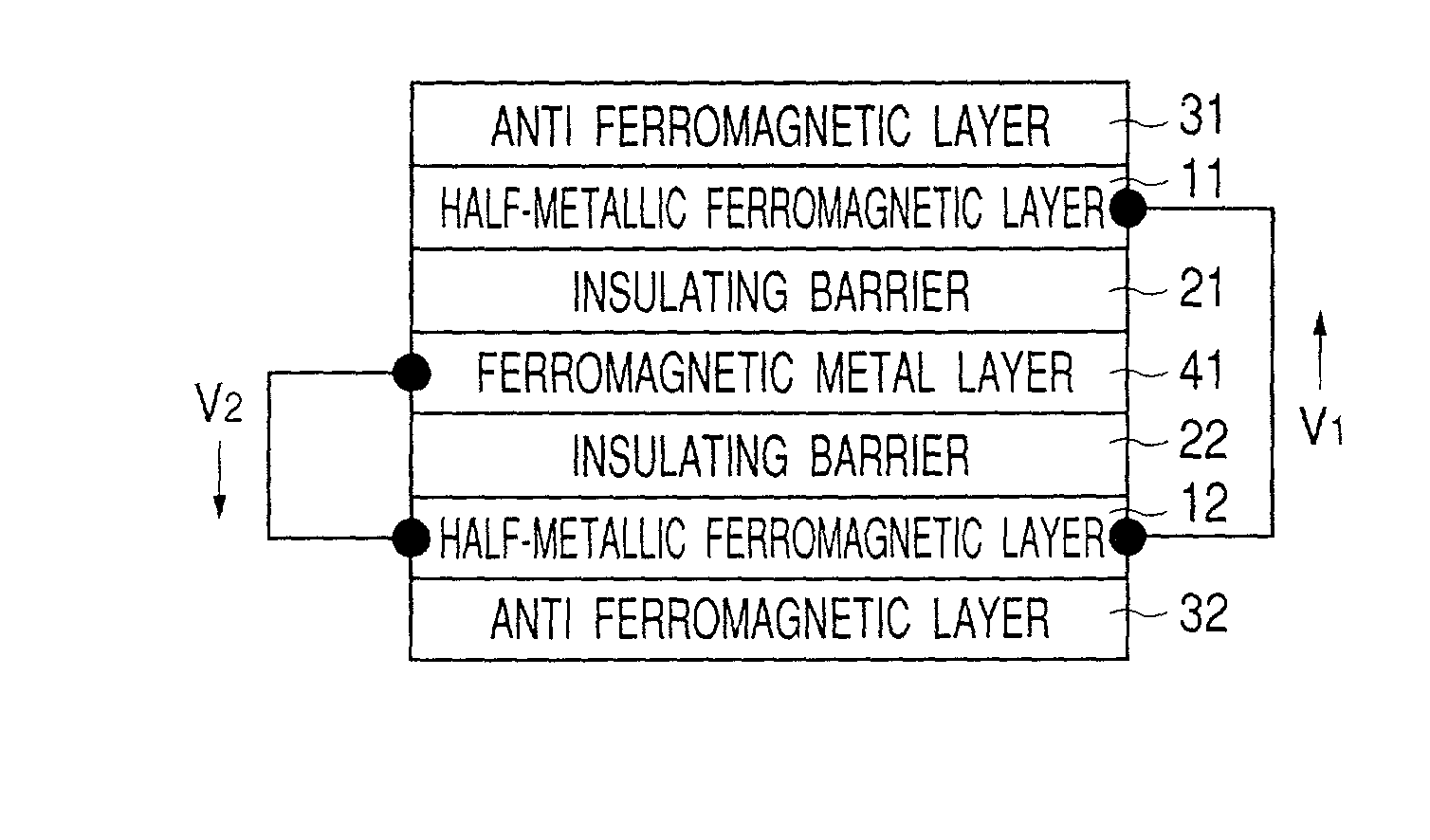
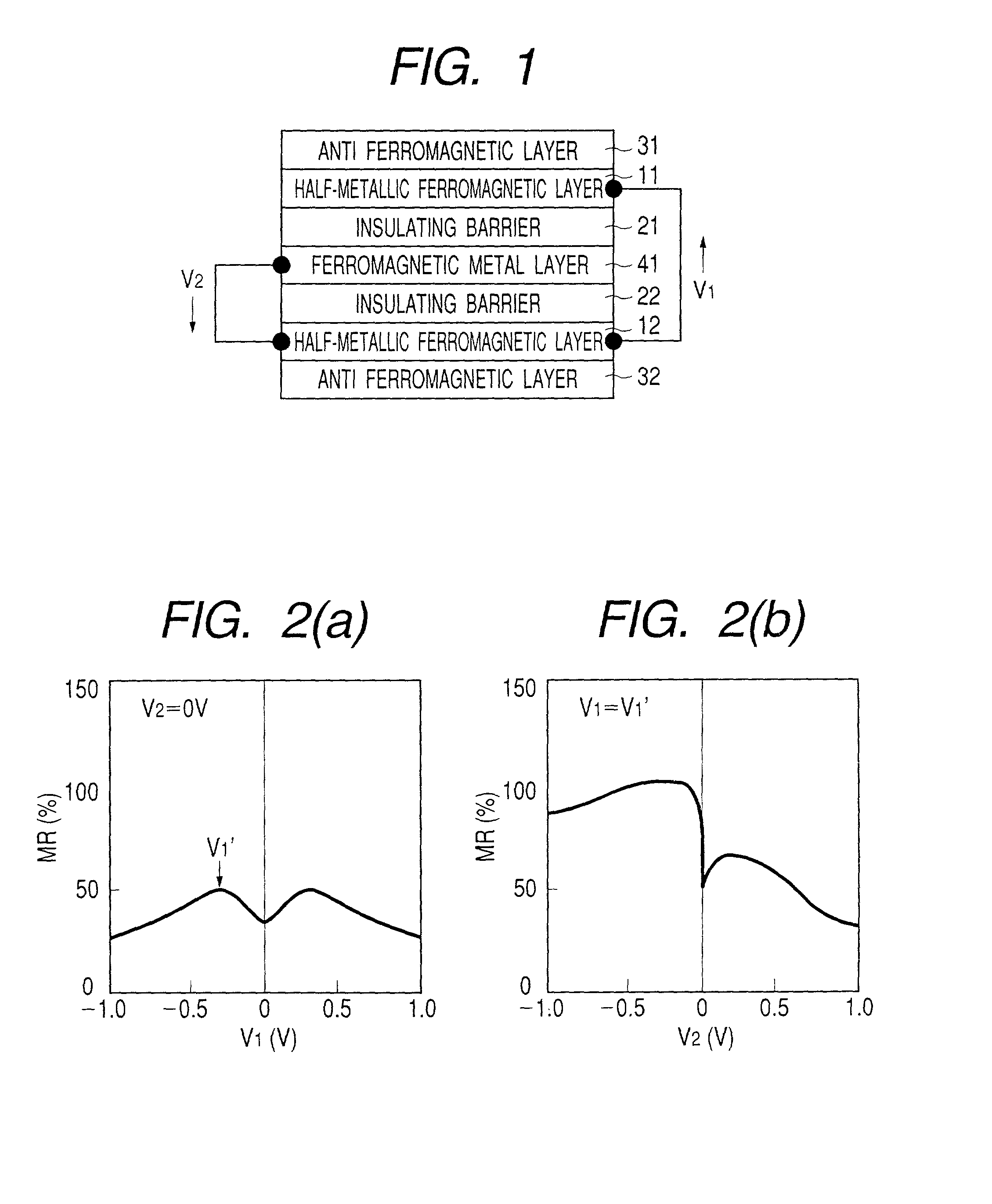
[0301] In the examples shown in FIGS. 18 to 34, each of the three-terminal TMR elements has a basic structure where a ferromagnetic metal layer, an insulating barrier layer, a half-metallic ferromagnetic layer, an insulating barrier layer and a ferromagnetic metal layer are laminated on a substrate in this order.
[0302] FIG. 18 is a schematic cross-sectional view showing other example of the three-terminal ferromagnetic tunnel element of the invention. The three-terminal TMR element of this example includes an antiferromagnetic layer 32 (30 nm), a ferromagnetic metal layer 42 (5 nm), an insulating barrier layer 22 (2 nm), a half-metallic ferromagnetic layer 11 (30 nm), an insulating barrier layer 21 (2 nm), a ferromagnetic metal layer 41 (5 nm), and an antiferromagnetic layer 31 (30 nm) laminated in this order on a substrate. An electrode terminal is formed in each of the ferromagnetic metal layers 41 and 42 to form an electric closed-circuit between the layers 41 and 42 (a bias volt...
embodiment3
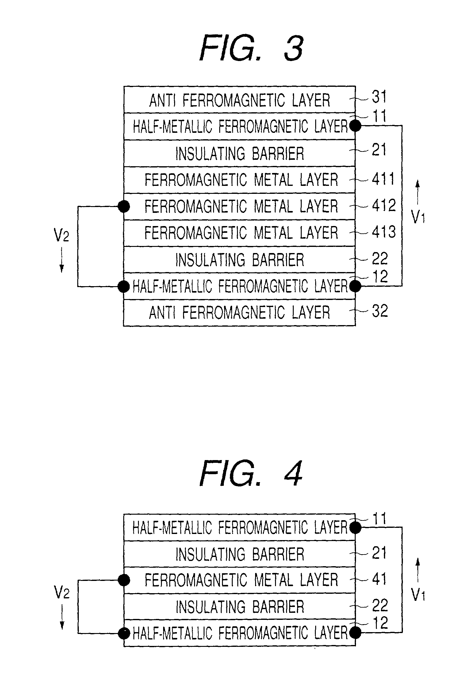
[0321] In the examples shown in FIGS. 35 to 99, each of the three-terminal TMR elements has a basic structure where a ferromagnetic metal layer, an insulating barrier layer, a ferromagnetic metal layer, an insulating barrier layer and a ferromagnetic metal layer are laminated on a substrate in this order.
[0322] FIG. 35 is a schematic cross-sectional view showing other example of the three-terminal ferromagnetic tunnel element of the invention. The three-terminal TMR element of this example includes an antiferromagnetic layer 32 (12 nm), a ferromagnetic metal layer 43 (3 nm), an insulating barrier layer 22 (1 nm), a ferromagnetic metal layer 42 (5 nm), an insulating barrier layer 21 (1 nm), a ferromagnetic metal layer 41 (3 nm), and an antiferromagnetic layer 31 (12 nm) laminated in this order on a substrate. An electrode terminal is formed in each of the ferromagnetic metal layers 41 and 43 to form an electric closed-circuit between the layers 41 and 43 (a bias voltage applied by th...
embodiment 4
[0388] In the examples shown in FIGS. 100 to 228, each of the three-terminal TMR elements has a basic structure where a half-metallic ferromagnetic layer, an insulating barrier layer, a ferromagnetic metal layer, an insulating barrier layer and a ferromagnetic metal layer are laminated on a substrate in this order.
[0389] FIG. 100 is a schematic cross-sectional view showing other example of the three-terminal ferromagnetic tunnel element of the invention. The three-terminal TMR element of this example includes an antiferromagnetic layer 32 (30 nm), a half-metallic ferromagnetic layer 11 (30 nm), an insulating barrier layer 22 (2 nm), a ferromagnetic metal layer 42 (10 nm), an insulating barrier layer 21 (1 nm), a ferromagnetic metal layer 41 (5 nm), and an antiferromagnetic layer 31 (12 nm) laminated in this order on a substrate. An electrode terminal is formed in each of the half-metallic ferromagnetic layer 11 and the ferromagnetic metal layer 41 to form an electric closed-circuit ...
PUM
 Abstract
Description
Claims
Application Information