Multi-mode control system for variable camshaft timing devices

Inactive Publication Date: 2002-07-11
BORGWARNER INC
View PDF0 Cites 21 Cited by
  • Summary
  • Abstract
  • Description
  • Claims
  • Application Information

AI Technical Summary

Problems solved by technology

First, there are shortcomings to using only the CTA powered VCT. The CTA device has a significantly lower frequency response than the OPA device, even though the potential actuation rate of the CTA device is substantially higher than the OPA device due to the larger amount of energy in the cam torque inputs. For example, inline four cylinder engines typically operate at relatively high speeds and therefore generate very high frequency torque pulses to which CTA systems do not respond quickly enough to cause actuation of the VCT. Thus, the relatively low frequency response of the CTA system results in a dramatic drop in CTA performance at the highe

Method used


Image

  • Multi-mode control system for variable camshaft timing devices
  • Multi-mode control system for variable camshaft timing devices
  • Multi-mode control system for variable camshaft timing devices

Examples


Embodiment Construction

[0037] In general, an hydraulic timing system is provided for varying the phase of one rotary member relative to another rotary member. More particularly, the present invention provides a multi-mode Variable Camshaft Timing system (VCT) that is powered by, or is responsive to, engine oil under pressure from a pump and / or from engine oil under pressure pulsations inherent as a result of the tongue pulsations that occur in a rotating camshaft. While the present invention will be described in detail with respect to internal combustion engines, the VCT system is also well suited to other environments using hydraulic timing devices. Similarly, the fluid medium described herein is preferably engine oil, but any other standard hydraulic fluid may be used. Accordingly, the present invention is not limited to only internal combustion engines.

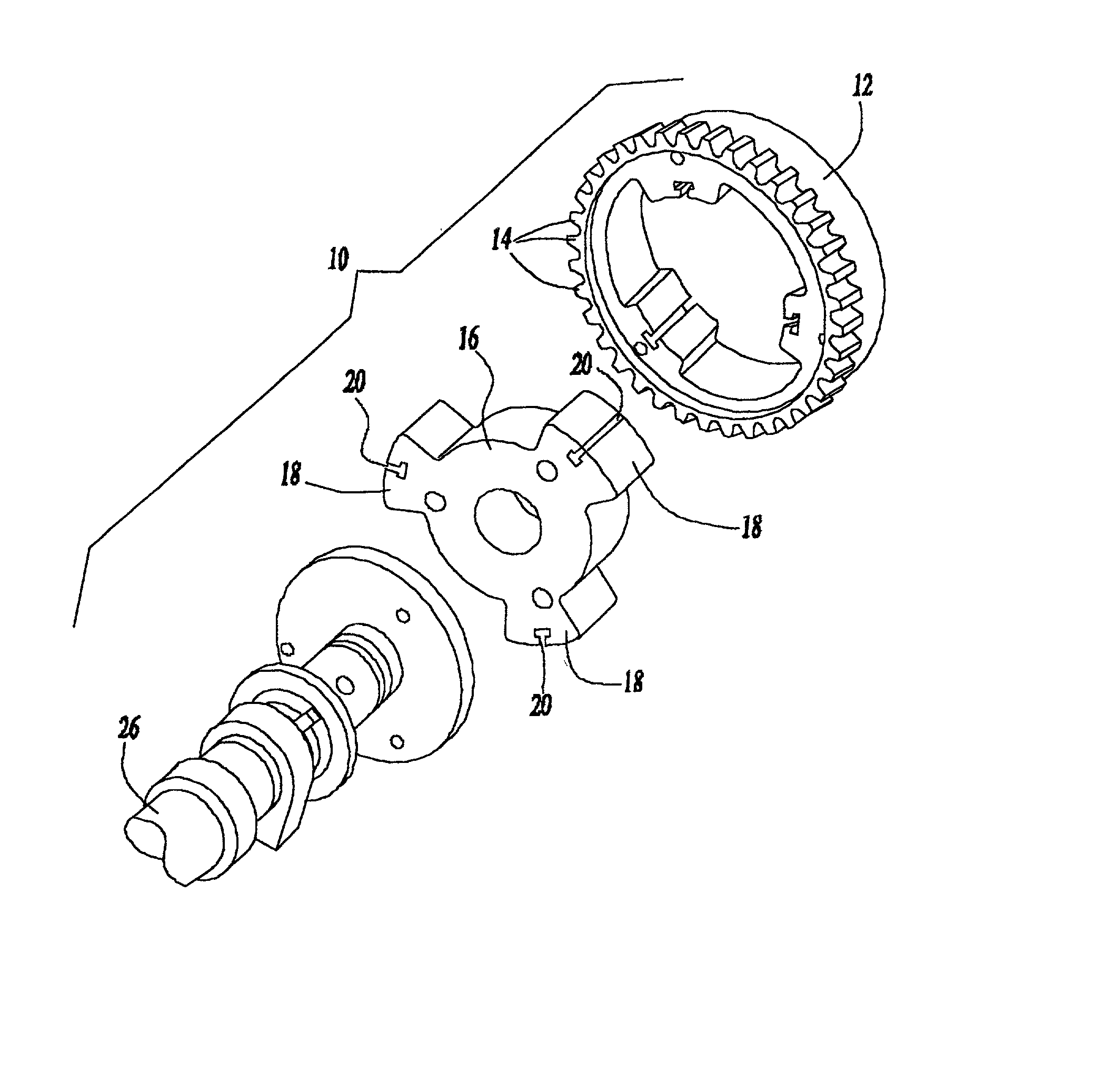
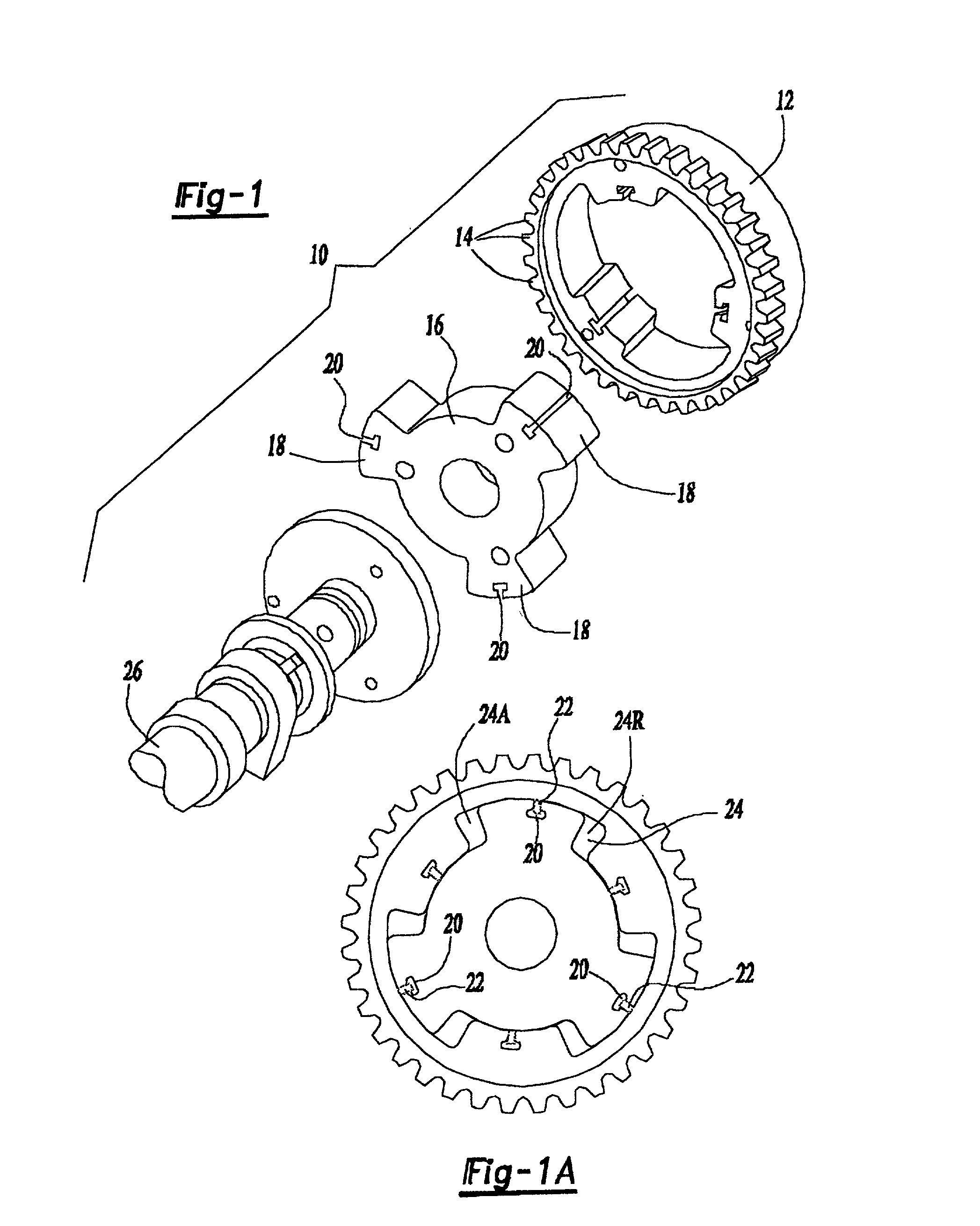
[0038] Referring now in detail to the Figures, there is shown in FIG. 1 a VCT apparatus 10 according to the preferred embodiment of the present inventio...


PUM


Abstract

A variable camshaft timing apparatus (10) includes a pulse actuating circuit (24A, 50, 44, 56, 60, 24R and 24R, 52, 46, 54, 58, 24A) for oscillating the variable camshaft timing apparatus in reaction to fluid under pulsation, and includes a pressure actuating circuit (30, 34, 36, 40, 44, 50, 24A, 24R, 52, 46, 66, 80/180, 32 and 30, 34, 38, 42, 46, 52, 24R, 24A, 50, 44, 64, 80/180, 32) for oscillating the variable camshaft timing device in reaction to fluid under pressure. Advance and retard valves (44, 46) are interconnected with the pulse and pressure actuating circuits for independently and simultaneously activating the pulse and pressure actuating circuits. Finally, an exhaust valve (80, 180, 280) is positioned in fluid communication with the pulse and pressure actuating circuits, such that the variable camshaft timing device may be oscillated using one or both of the pulse actuating and pressure actuating circuits, and may be maintained in position using one or both of the pulse actuating and pressure actuating circuits.

Description

[0001] This application is based, in part, on co-pending provisional U.S. Patent application No. 60 / 260,039 (attorney docket DKT00011), which was filed on Jan. 8, 2001.[0002] 1. Field of the Invention[0003] The present invention generally relates to an internal combustion engine having a control system for controlling the operation of a variable camshaft timing mechanism (VCT) of the type in which the position of a camshaft is circumferentially varied relative to the position of a crankshaft. More specifically, this invention relates to control systems for operating VCT devices in response to fluid under continuous pressure and fluid under pulsation to selectively advance, retard, or maintain the position of the camshaft.[0004] 2. Description of the Prior Art[0005] It is known that the performance of an internal combustion engine can be improved by the use of dual overhead camshafts, one to operate the intake valves of the various cylinders of the engine and the other to operate the...

Claims


Application Information

Patent Timeline
IPC IPC(8): F01L1/344F01L1/34
CPCF01L1/34F01L1/344F01L2001/34426Y10T74/2102F01L1/34409F01L1/3442F01L2001/3443F01L2250/04F01L2250/06
Inventor SMITH, FRANK R.WING, BRAMAN C.GARDNER, MARTYDUFFIELD, MIKE
Owner BORGWARNER INC
Why Eureka
Try Eureka