Water sprinkler head with integral off-on water flow control valve and adaptive fittings therefor

a technology of water sprinkler head and water flow control valve, which is applied in watering devices, horticulture, agriculture, etc., can solve the problems of screen needing periodic cleaning, up the orifice, and becoming los

Inactive Publication Date: 2002-07-11
SIRKIN TEODORE
View PDF5 Cites 36 Cited by
  • Summary
  • Abstract
  • Description
  • Claims
  • Application Information

AI Technical Summary

Benefits of technology

0035] It is, therefore, one of the primary objects of the present invention to provide a sprinkler head which allows for gradual cessation and re-initiation of water flow to a sprinkler head from a point upstream of the insert of the sprinkler head, but yet in close proximity to the insert of the sprinkler head.

Problems solved by technology

Water lines which carry water delivered from sources, such as the municipal water supply, or from wells, frequently carry small particles of dirt, pebbles, organic matter, pipe corrosion accumulations, installation tailings and other debris.
This debris, left unchecked, quickly clogs up the orifices and nozzles of sprinkler heads rendering them unoperational.
The problem, is so ubiquitous that virtually every commercially available plastic sprinkler head, both domestic and foreign, is constructed with a built-in screen, or contains a removable screen, in order to filter out debris so as to avoid clogging the orifices of the nozzles and inserts.
However, inasmuch as the screen collects this debris contained in the delivered water, the screen necessarily requires periodic cleaning.
Insofar as removable screens are concerned, during maintenance operations, it is common for them to become lost or not be replaced due to oversight, which allows the debris to travel directly to the area of the orifices of the insert or nozzle.
Even with screens in place, very small pieces of debris often get through the screen and bind together between the screen and the orifice to eventually clog up the orifice.
Sprinkler heads placed at ground level also suffer clogged orifices due to small stones and insects entering the orifices from the area surrounding the heads and then becoming stuck within.
This cannot be accomplished with pop-up shafts, but only on stationary shrub heads.
Also, a great deal of water is wasted in this manner.
In some cases, time clocks are installed inside of a locked building for which the landscaping is provided, thereby interfering with proper maintenance.
As can easily be seen, a great deal of effort must be expended for cleaning out sprinkler heads where the valve or time clock for the project may be located at a somewhat remote point from the sprinkler head being serviced.
At present, there is nothing available in the sprinkler head industry that provides for turning the water supply on and off at the immediate location of the sprinkler head, upstream of the insert or nozzle, in a manner which provides for complete flushing of the water passageway duct after removal of the insert.
This latter design comprises a large rotor-driven head for covering large areas and does not appear easily adaptable to small garden and planter-type sprinkler heads and ordinary insert-types of pop-up heads and cannot be applied to retrofittable fittings.
This product does not allow for the valve mechanism to be anterior to or upstream to the screen, even if the screen were moved to a location close to the nozzle.
The aforesaid sprinkler head design also does not allow for thorough flushing of the water passageway duct anterior to the insert or nozzle area without an expansive and time-consuming process of removing the gear driven rotor assembly located in the passageway chamber.
However, the nozzle-receiving cavity and adjusting mechanism is machine-pressed into place and requires special tools for its removal.
Beyond the foregoing, there is no commercially available sprinkler head which allows for gradual shutting off the water to the insert or to an insert area which is valve-operated.
Further, no sprinkler head or pop-up shaft provides for thorough, unobstructed controlled flushing of the water passageway duct anterior to the insert or nozzle.
When debris clogs up those small holes, removal of the entire pop-up shaft becomes necessary to flush out the pop-up shaft.
Naturally, this requires shutting down the water supply to the entire system.
This type of construction is difficult to use with ordinary stationary shrub-type sprinkler heads.
It can be observed that the amount of the personnel hours lost in the pure physical act of walking back and forth can be quite substantial and necessarily adds to the cost of an irrigation bill from the maintenance personnel or the like.
Moreover, it consumes a substantial amount of effort and, in some cases, frequently results in malfunctioning sprinkler heads not being cleaned and repaired as frequently as they would otherwise be repaired or cleaned.
In addition to the foregoing, pop-up sprinkler heads are much more complicated in their construction than are the so-called "shrub heads".
Other than the very top of the head, pop-up heads are completely buried in the ground making them more difficult to service.
However, in each of these cases, one could not remove the head or the insert of the head since there is no upstream point in proximity to the sprinkler head to cut-off water flow for a temporary period.
However, none of these sprinkler head types include any means to stop water flow to the insert at a nearby point upstream from the sprinkler head insert.
However, and here again, there is no means to cut-off water flow to the head at a point adjacent to and upstream of the sprinkler head insert.
However, in the Fuller patent, the screw serves as a restrictor and only balances the amount of water which exits the nozzle of the head.
Notwithstanding, the device in the Fuller patent would not function to work as an off-on valve for temporarily allowing servicing of a sprinkler head.
The head, however, is a one piece sprinkler head such that there could be no facility for cleaning the head or changing any part of the head.

Method used


Image

  • Water sprinkler head with integral off-on water flow control valve and adaptive fittings therefor
  • Water sprinkler head with integral off-on water flow control valve and adaptive fittings therefor
  • Water sprinkler head with integral off-on water flow control valve and adaptive fittings therefor

Examples


Embodiment Construction

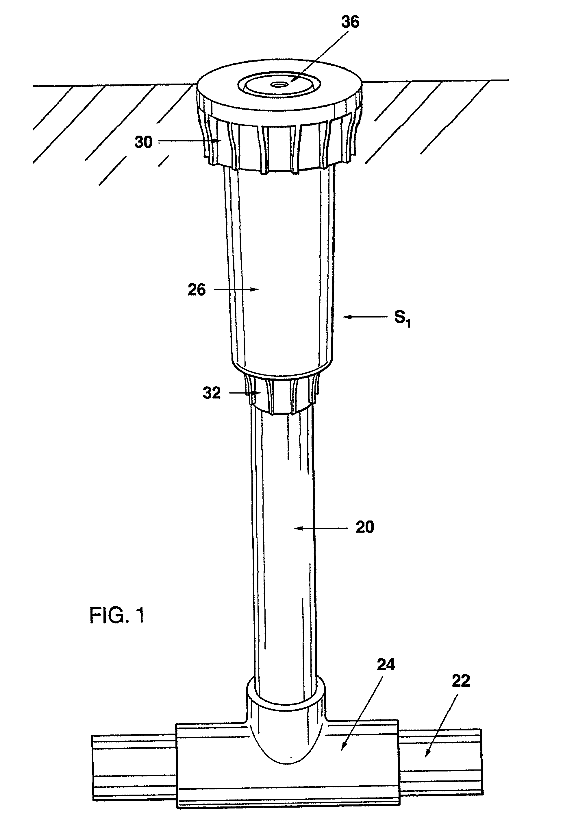
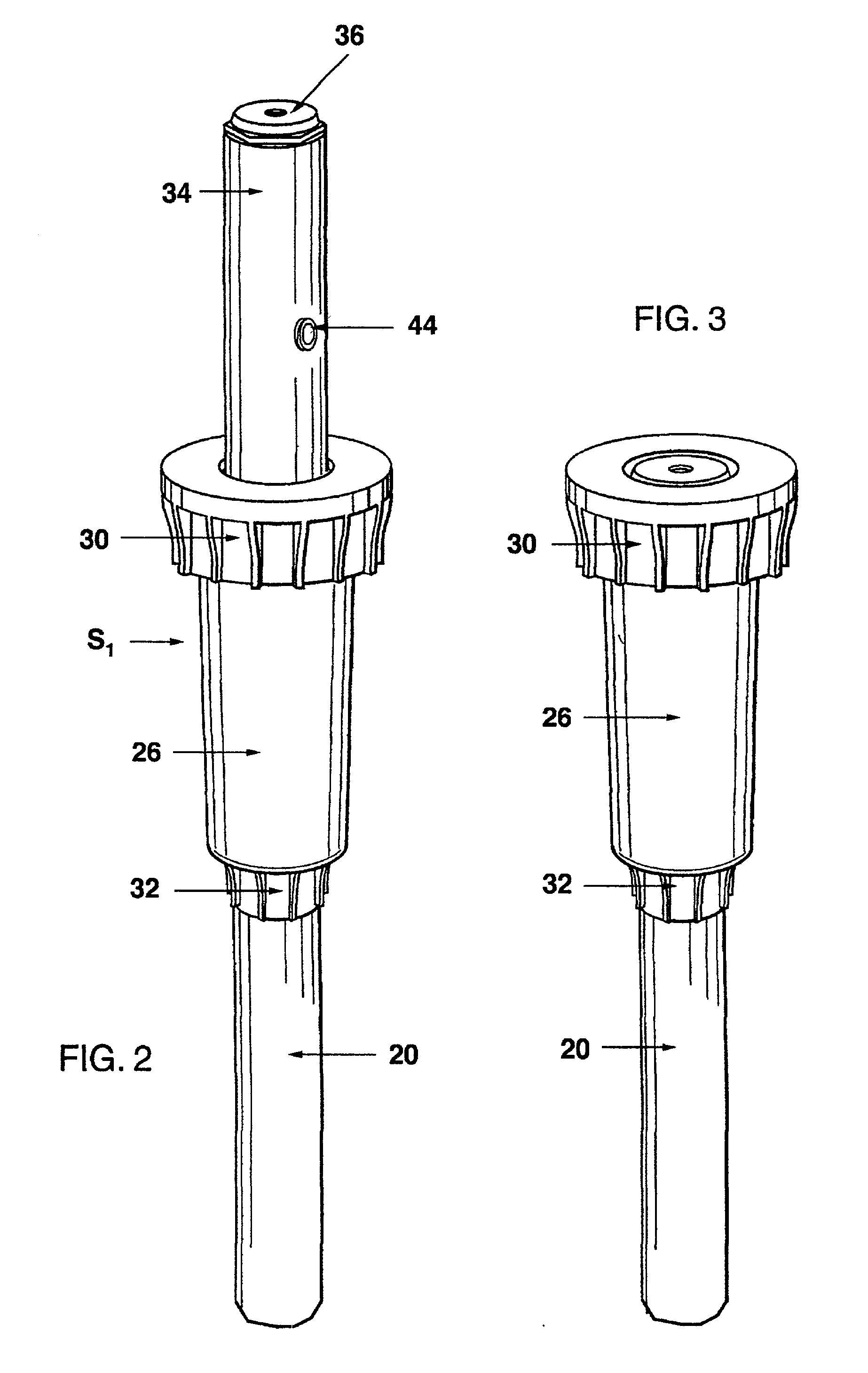
[0076] Referring now in more detail and by reference characters to the drawings, which illustrate preferred embodiments of the present invention, FIG. 1 illustrates a pop-up sprinkler head S.sub.1 constructed in accordance with and embodying the present invention and shown as being connected to the upper end of a riser pipe 20 and which is, in turn, supplied with water from the main subterranean irrigation line 22. Typically, the riser pipe 20 is connected to the irrigation line 22 through a T-fitting 24.

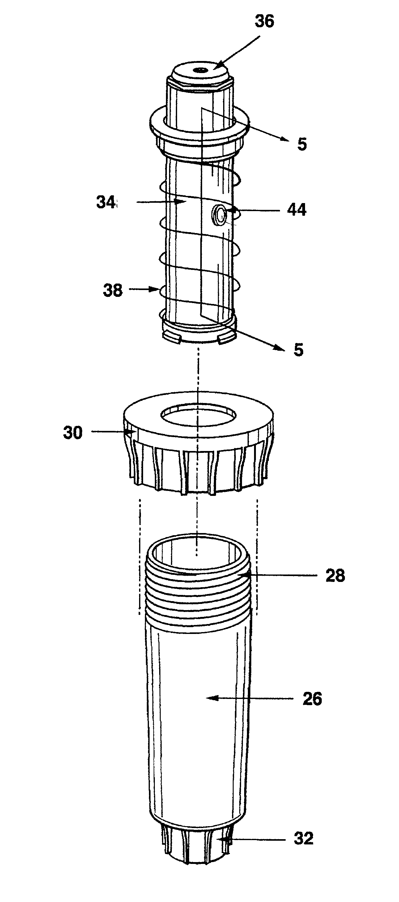
[0077] The pop-up sprinkler head S.sub.1 is provided with an outer body or so-called "housing" 26 threadedly secured to the upper end of the riser pipe 20 and the open end of the body 26 is provided with a threaded section 28 for threadedly receiving a removable cap 30. The lower end of the body 26 is provided with an integral internally threaded fitting 32, the latter of which allows for threaded attachment to the upper portion of the riser pipe 20 as aforesaid.

[0078] Provided for ...


PUM


Abstract

A sprinkler head assembly comprised of a base located at the upper end of a riser tube and which base carries an insert with an opening allowing for distribution of water. In accordance with the present invention, a control valve is located directly at the sprinkler head assembly. The control valve may be located in a stationary or shrub head which would be connected to a base or otherwise to a riser tube. The control valve could be located in a pop-up shaft, pop-up sprinkler head, or in a retrofit coupling or adapter located between a riser tube and sprinkler head. The control valve would rely upon a screw capable of being threadedly moved into a duct generally perpendicular thereto and which would have a diametral size somewhat larger than the duct. Moreover, the screw would be provided with an opening having a diameter approximately equal to that of the duct. The opening would be alignable with the duct in one position and when rotated would completely block the flow in another position. In this way, water flow to the sprinkler head assembly may be temporarily interrupted.

Description

[0001] 1. Field of the Invention[0002] This invention relates in general to certain new and useful improvements in water sprinkler heads and, more particularly, to an improved sprinkler head which allows for turning water flow off and on directly at the sprinkler head to enable removal of the spray distributor, or disc, or so-called "insert" and, in some cases, the filtering screen underlying the insert.[0003] 2. Brief Description of Related Art[0004] Lawn and garden sprinkler systems are common in many parts of the United States and in many other countries where the climate is hot and grass or other vegetation would readily perish if not watered either physically by one or more individuals or through the aid of an irrigation sprinkler system. Sprinkler systems are also more frequently used in periods in which the climate is particularly hot during certain periods of the year.[0005] All irrigation sprinkler systems are connected to a water source, such as a municipal water supply, a...

Claims


Application Information

Patent Timeline
Patent Type & Authority Applications(United States)
IPC IPC(8): B05B1/30B05B15/10
CPCB05B1/30B05B1/3026B05B15/10B05B15/74
Inventor SIRKIN, TEODORE
Owner SIRKIN TEODORE
Why Eureka
Try Eureka