
System of and method for decoding trellis codes

Active Publication Date: 2002-07-18
ENTROPIC COMM INC
View PDF10 Cites 81 Cited by
  • Summary
  • Abstract
  • Description
  • Claims
  • Application Information

AI Technical Summary

Benefits of technology

[0084] The timing and manner in which the backward engines perform their operations in the particular example are indicated in the figure. For example, during time T.sub.0-T.sub.1, backward engine 651a performs acquire processing of sub-block L.sub.1-L.sub.2, and during time T.sub.1-T.sub.2, it performs reliable processing of sub-block L.sub.0-L.sub.1. Concurrently with these functions, backward engine 651b, during time T.sub.1-T.sub.2, performs acquire processing of sub-block L.sub.2-L.sub.3, and during time T.sub.2-T.sub.3, performs reliable processing of sub-block L.sub.1-L.sub.2.

Problems solved by technology

Known decoders of TCM codes are configured to handle QPSK symbols, but are susceptible to performance limitations in applications involving MPSK or QAM symbols beyond QPSK.
The problem is particularly acute in applications involving log-MAP decoders, in which probabilities are expressed in the natural log domain.
The computations needed to perform log-domain calculations places additional demands on the decoders.

Method used


Image

  • System of and method for decoding trellis codes
  • System of and method for decoding trellis codes
  • System of and method for decoding trellis codes

Examples


first embodiment

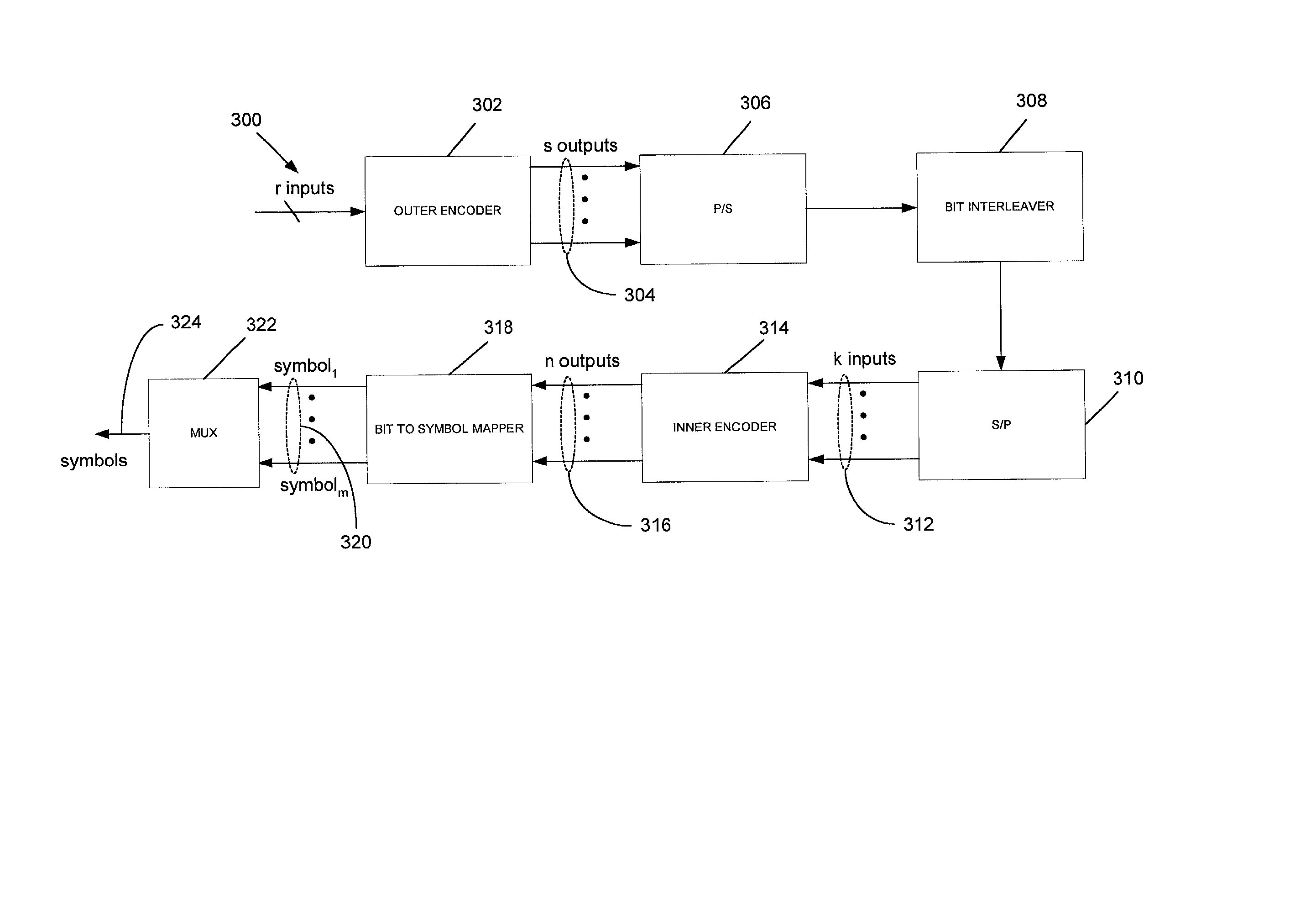
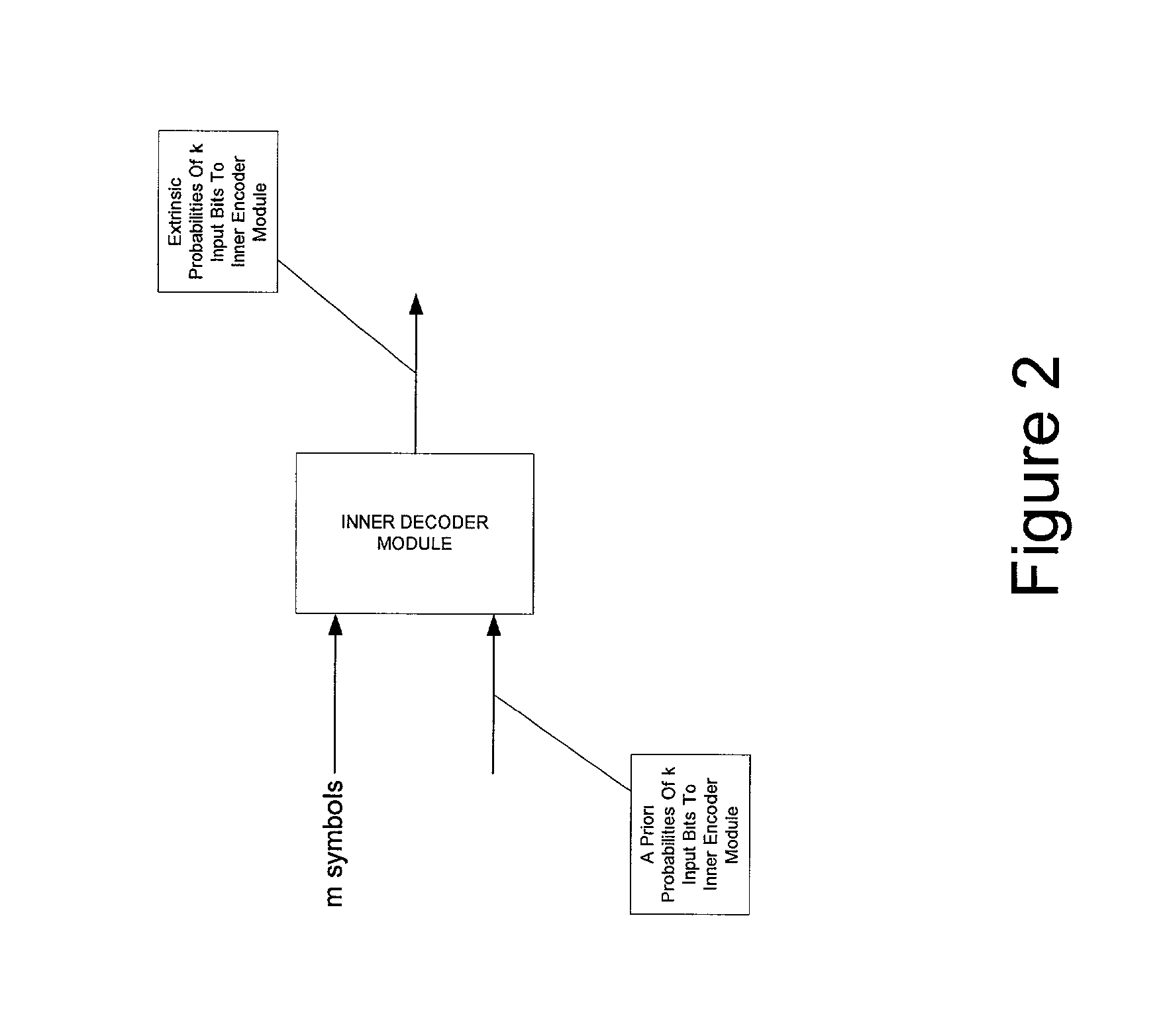
[0091] a decoding system according to the invention is illustrated in FIG. 7A. In this embodiment, m TCM encoded symbols, identified in the figure with numeral 704, are input to the system along with a priori probabilities for k source bits, identified in the figure with numeral 706, where both m and k are integers of one or more. The m symbols may result from passing the k source bits through a TCM encoder which, for purposes of this disclosure, is the combination of a rate k / n convolutional encoder and a bit to symbol mapper which maps the n output bits from the convolutional encoder into m symbols. (One example of a TCM encoder is the combination of inner encoder module 314 and mapper 318 in FIG. 3, but it should be appreciated that a TCM encoder is not limited to serving as the inner encoder in a SCTCM encoder, and that other applications are possible, including where the TCM encoder operates in a standalone mode.) The symbols may also have been transmitted over a wireless or wi...

second embodiment

[0129] a system according to the invention is illustrated in block diagram form in FIG. 7B. Four dimensional quadrature symbols, identified in the figure with numeral 720 and represented as I.sub.X Q.sub.X , I.sub.Y , and Q.sub.Y , are input to branch metric logic 724. The symbols may comprises two 8-PSK symbols as produced from a TCM encoder comprising the series combination of a rate 5 / 6 convolutional encoder and a bit to symbol mapper for mapping each 6 bit output of the convolutional encoder into 2 8-PSK symbols. Such an encoder is an example of the encoder illustrated in FIG. 4 and previously described.

[0130] A priori probabilities for the 5 bits which gave rise to the two 8-PSK symbols, identified in the figure with numeral 722 and represented as .lambda., are also input to the branch metric logic 724.

[0131] The branch metric logic 724 is configured to produce, in parallel, branch metrics for each of the branches in the portion of the trellis corresponding to the inputs 720 an...


PUM


Abstract

Systems and related methods are described for (1) determining one or more state probabilities for one or more states in a trellis representation; (2) determining an estimate of or extrinsic output for one or more bits using a trellis representation; (3) determining a branch metric for a branch in a trellis representation; (4) performing a MAX*2->1 operation; (5) performing a MAX*2p->1 operation, where p is an integer of two or more, through a hierarchical arrangement of MAX*2->1 operations; and (6) computing forward state probabilities in a forward mode of operation and computing backward state probabilities in a backward mode of operation. Combinations of the foregoing are also described.

Description

[0001] This application claims the benefit of U.S. Provisional No. To Be Determined, Howrey Dkt. No. 01827.0047.PZUS02, filed Nov. 13, 2001 (as Howrey Dkt. No. 01827.0047.NPUS00), U.S. Provisional Application No. 60 / 327,258, Howrey Dkt. No. 01827.0047.PZUS01, filed Oct. 4, 2001, and U.S. Provisional Application No. 60 / 255,797, Howrey Dkt. No. 01827.0047.PZUS00, filed Dec. 15, 2000, each of which is hereby filly incorporated by reference herein as though set forth in full.1. FIELD OF THE INVENTION[0002] This invention generally relates to decoders, and, more specifically, to decoders of trellis codes.2. RELATED ART[0003] Trellis codes, such as convolutional codes, or parallel or series combinations or concatenations of convolutional codes, are codes which are decoded through use of a trellis. Trellis coded modulation (TCM) codes are groupings of trellis coded bits which result from mapping the bits into symbols, such as MPSK symbols, prior to transmission. The symbols may then be use...

Claims


Application Information

Patent Timeline
IPC IPC(8): H03M13/29H03M13/39H03M13/41H04L1/00
CPCH03M13/2957H03M13/2972H03M13/3905H03M13/3927H03M13/3961H03M13/3972H03M13/6572H04L1/005H04L1/006H04L1/0065
Inventor ARAD, ERANDALUMI, EFRAIMKONS, SHACHAREIDSON, DONALD B.
Owner ENTROPIC COMM INC
Learn More