Optical patternation method

a patterning and optical technology, applied in the field of optical techniques, can solve the problems of under-representation of the amount of material that is actually present, the amount of exciting laser light can be considerably reduced, and the scattering of light is not uniform,

Inactive Publication Date: 2002-08-22
TALLEY DOUGLAS G +2
View PDF9 Cites 15 Cited by
  • Summary
  • Abstract
  • Description
  • Claims
  • Application Information

AI Technical Summary

Problems solved by technology

Optical patternation techniques, however, generally suffer from shortcomings related to the scattering of light.
If enough particles are present, the amount of the exciting laser light can be considerably reduced, resulting in an under-representation of the amount of material that is actually present.
Secondly, some of the emitted LIF and / or scattered light will be reabsorbed and / or scattered by particles within the field before reaching the optical detector, leading to a further under-representation of the amount of material that is actually present.
Third, light scattered by particles illuminated by the laser strike other particles not directly illuminated by the laser.
Practical limitations, for example, may not allow the optical access necessary to collect the signals at 90 degrees.
However, the fluorescence signal would also decrease, and the beam path may exceed the depth of field of the imaging optics.
Therefore, the collection angle will be assumed here to be 90 degrees, although the methodology described above can be applied with increasing difficulty as the collection angle deviates from 90 degrees.
The error bars on the PDI results show expected error based on measurements variation in size at several locations.
This variation also leads to problems in establishing a suitable "reference ratio" which is the PDI measured D32 value assigned to a given value of the ratio of the fluorescence signal magnitude to the scattering signal magnitude.
In a dense particle field, even the rather small sample volume of the PDI (200.times.200 .mu.m.sup.2) can possess multiple drops, thereby leading to problems with counting efficiency.

Method used


Image

  • Optical patternation method
  • Optical patternation method
  • Optical patternation method

Examples


Embodiment Construction

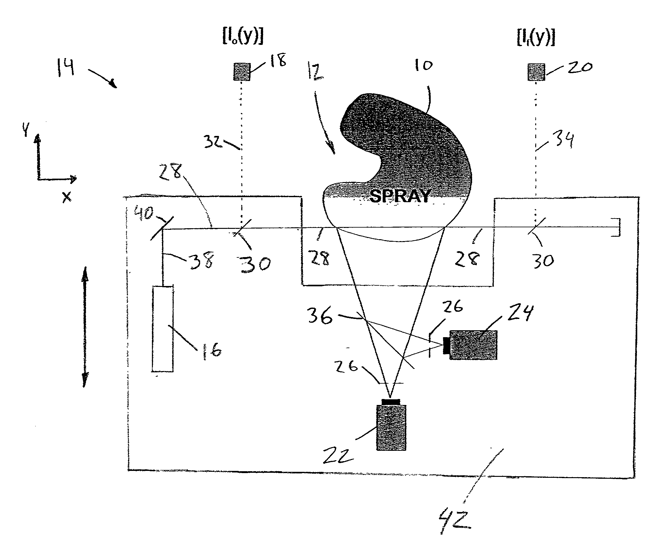
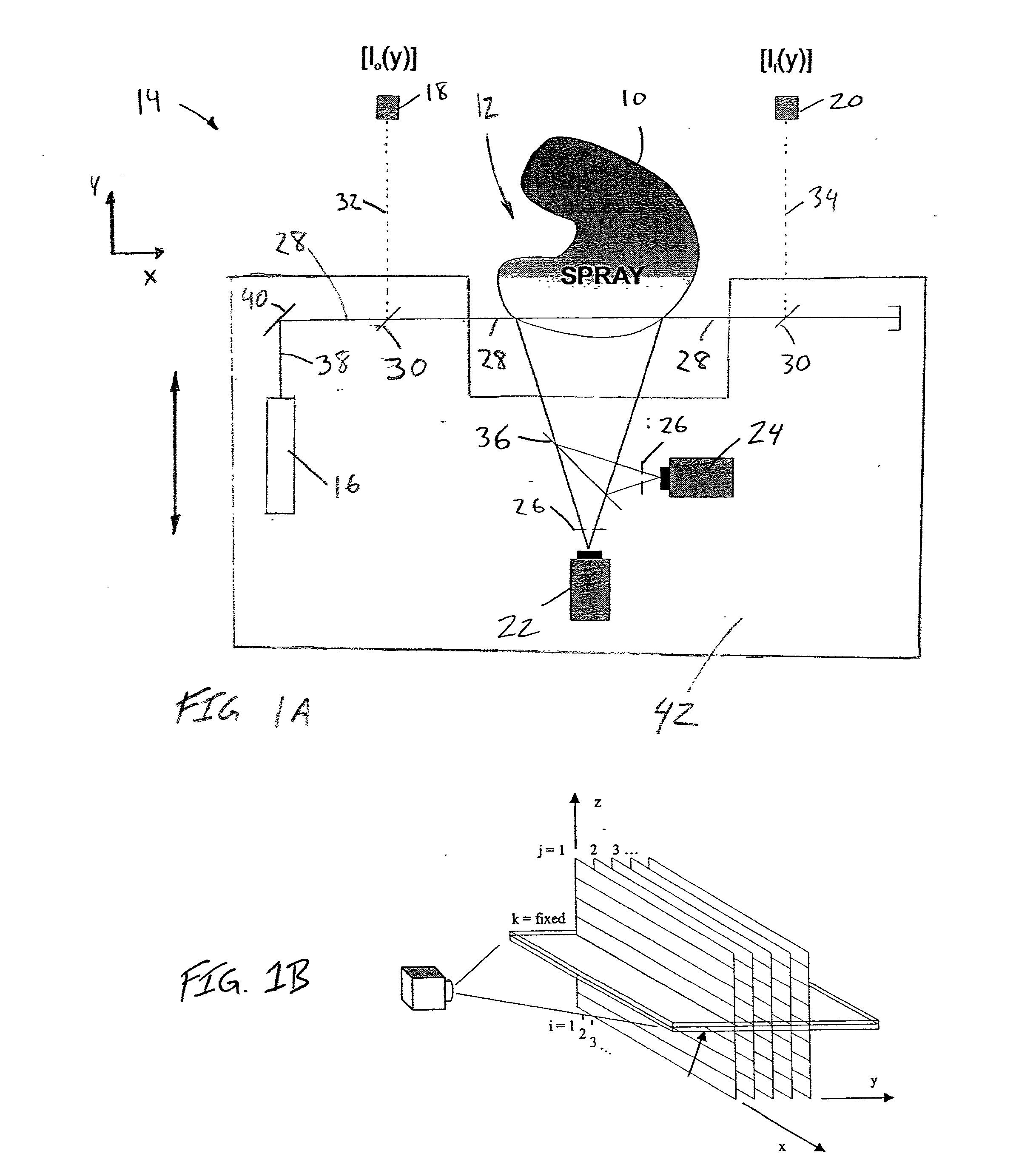
[0103] A simplified example demonstrating the application of this method is presented below. An arbitrary three-dimensional field 50 comprising the region 12 containing, for example, a particle field 10, can be represented in a discretized format as shown in FIG. 10. A specific plane of interest 52 cutting through the field 50 is shown. In this case, for convenience, the plane 52 is parallel to the x-y axes.

[0104] A systematic interrogation of this plane of interest 52 can be executed using a beam of light 38 rather than a sheet and by placing the detector 22, 24 in the same plane as the plane of interest as illustrated in FIGS. 11A and 11B.

[0105] The method described above involves a systematic collection of images of both scattered light and fluorescence. The systematic collection comprises obtaining images at various discrete locations moving into the 3D field 50 as depicted in FIGS. 12A-12C where three of five measurement "stations," referred to above as optical paths 28, are sh...


PUM

PropertyMeasurementUnit
collection angleaaaaaaaaaa
distanceaaaaaaaaaa
poweraaaaaaaaaa

Abstract

To measure property-specific distributions like surface area and mass concentrations, in a particle field that attenuates light passing therethrough, such as a spray or aerosol, a probe beam having a suitably selected wavelength is directed into and thereby caused to interact with the particle field. Light produced by this interaction is detected by sensors separated a distance from the beam. Extinction of the probe as it propagates through the particle field is quantified by determining the amount of light exiting the field in comparison with the amount of light entering the field. The property specific concentrations are determined from the light detected by the sensors after correcting for the extinction of the beam as well as attenuation of the light traveling the distance from the beam to the sensors. The light produced by the interaction of the probe with the particle field may include scattering, fluorescence, or both. Further, methods enable the user to determine the mass and surface area distributions of a spray or aerosol by traversing a single laser beam through the ensemble of particles to be investigated.

Description

PRIORITY APPLICATION[0001] This application claims priority under 35 U.S.C. .sctn.119(e) from U.S. Provisional Patent Application 60 / 233,611 filed Sep. 18, 2000.[0002] 1. Field of the Invention[0003] The invention relates to what is referred to herein as "patternation," performing quantitative measurements of the specific properties of particles, e.g., surface area and / or mass distributions, within a particle field such as a spray, including dense particle fields. More particularly, the invention relates to an optical technique for determining such distributions.[0004] 2. Description of the Related Art[0005] Particle fields comprising collections of particles, such as liquid particles or droplets in sprays, are encountered in many aspects of daily life. Sprays and other particle fields are associated with water sprinklers, paint sprayers, chemical process plants, medicinal coatings for tablets and pills, aerosols for inhalation therapy, lubrication, cooling, fabrication techniques u...

Claims


Application Information

Patent Timeline
Patent Type & Authority Applications(United States)
IPC IPC(8): G01N15/00G01N15/02G01N15/06
CPCG01N15/0205G01N15/06G01N2015/0026G01N2015/0693
Inventor TALLEY, DOUGLAS G.MCDONELL, VINCENT G.SAMUELSEN, G. SCOTT
Owner TALLEY DOUGLAS G
Why Eureka
Try Eureka