Collector and separator apparatus for lawn and garden
a technology of separator and lawn and garden, which is applied in the direction of gas current separation, turf growing, grain treatment, etc., can solve the problems of difficult to remove thick layers of debris, difficult to collect leaves and other debris, and no longer so effective in collecting leaves and other debris close to the ground, etc., and achieve the effect of effectively removing deep piles of leaves and other debris
- Summary
- Abstract
- Description
- Claims
- Application Information
AI Technical Summary
Benefits of technology
Problems solved by technology
Method used
Image
Examples
example 2
[0126] Following the experience of example 1, collecting leaves with a conventional 26-inch, two-stage snow blower was attempted to see if the auger-feed mechanism would function with leaves. Indeed, the auger readily fed even the deepest piles of leaves into the second-stage blower, which blew them 10-15 feet away. However, this approach left a thin layer of leaves and other debris on the lawn where the pick-up auger had passed.
[0127] The conclusion was that a machine with a similar auger-feed pick-up would collect even deep piles of leaves. However, the user would need to go over the lawn a second time with a different machine to collect the thin layer of residual leaves and other debris.
example 3
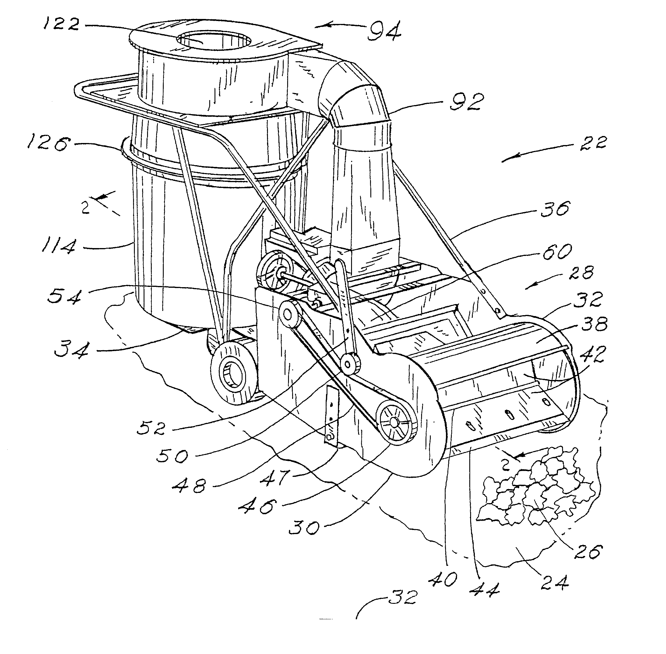
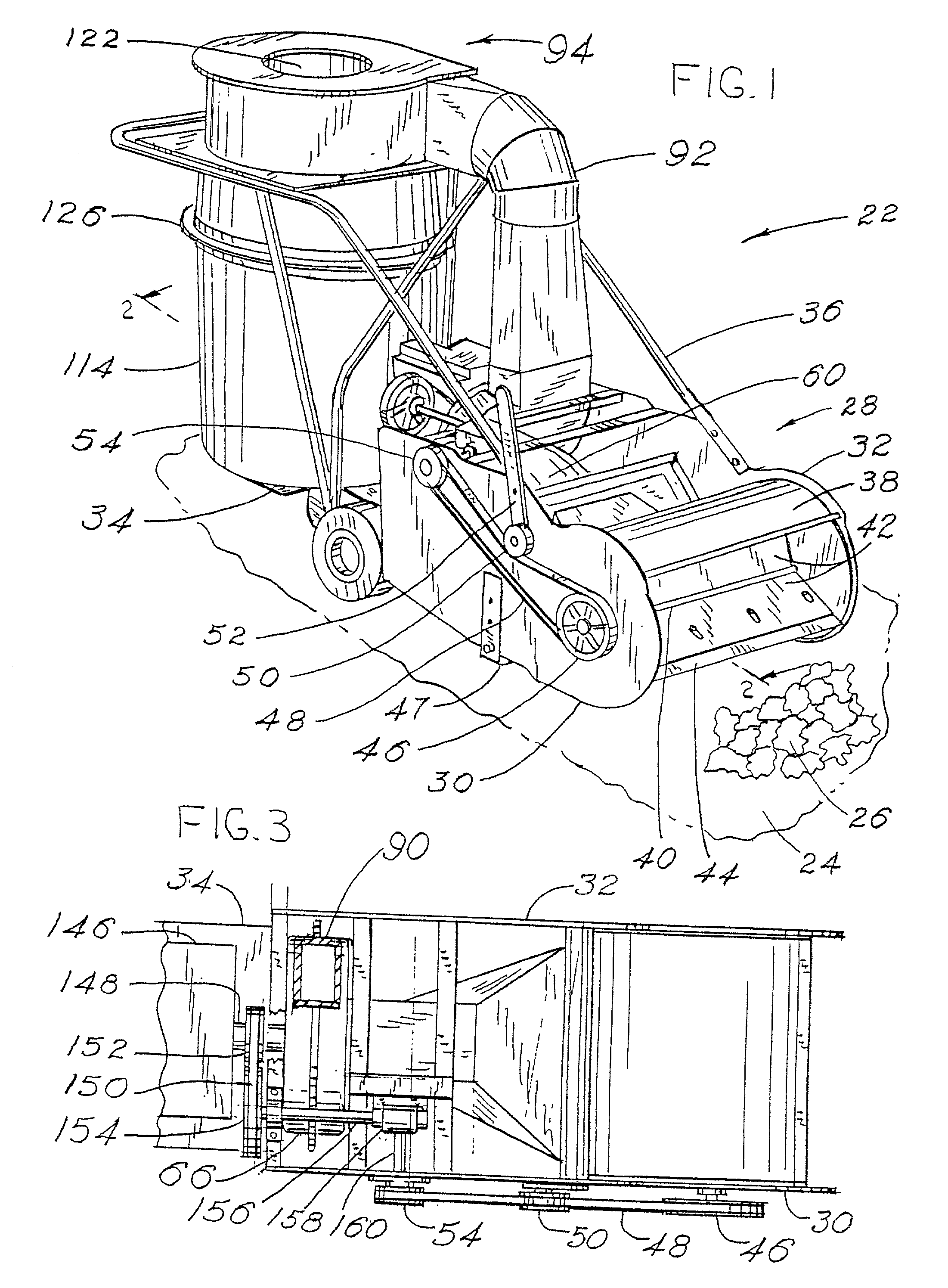
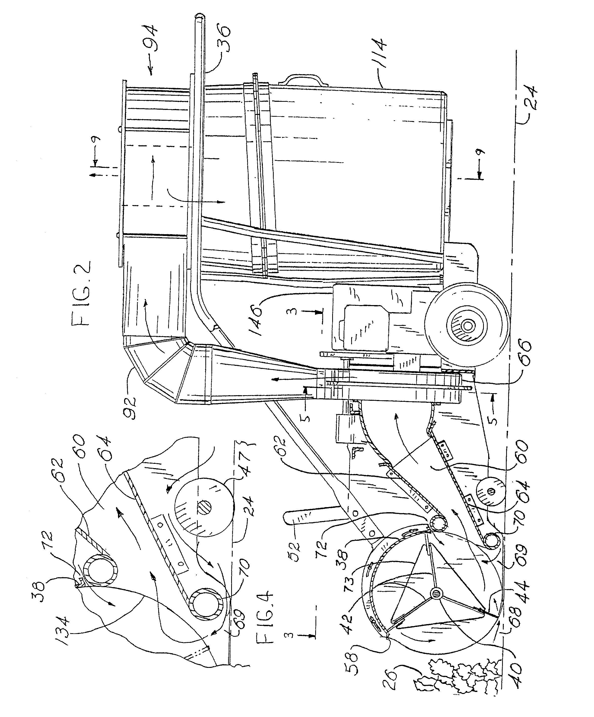
[0128] A machine of the current invention was built according to the drawings in FIGS. 1-11. A Yard Man 5-horsepower chipper-shredder-vacuum machine built by MTD Products was purchased; the chipper-shredder unit and attached drive motor were removed from the purchased machine; and then they were mounted on the base plate of the current machine. The machine width between the left support plate and the right support plate was 24." The collector rotor diameter was 15", and it turned 65 revolutions per minute. The front, upper edge of the housing over the rotor was about 131 / 2" above the support surface. The lowermost portion of the lower collector lip was about 1" above the supporting surface when measured with the machine sitting on a concrete slab. The collector duct had an entrance opening 21 / 2" high and 24" wide with a cross sectional area of 60 square inches, an exit opening about 6" high and 9" wide with a cross sectional area of about 54 square inches, and a convergence angle of...
example 4
[0131] The machine of Example 3 was modified as follows: In order to increase the air flow rate, (1) the engine speed was increased from 3450 to 3680 revolutions per minute; (2) the constriction in the primary separation loop was removed, leaving the channel size throughout the loop at 4" wide and 8" high; (3) the transfer opening was enlarged to about 100 square inches; and (4) the separator exhaust port was enlarged from 7" to 91 / 8" diameter. The airflow rate was then measured at 1000 cubic feet per minute (41.7 cfm per inch of machine width). The collector rotor speed was increased from 65 to 276 revolutions per minute. In order to reduce the number of leaves carried over the top of the turning collector rotor, the stripping slot was opened to 1". The diameter of the baffle in the separator was reduced, leaving an annular radial clearance of about 23 / 8" between the baffle perimeter and the outside wall of the secondary chamber. The perimeter of the baffle was 51 / 4" below the ceil...
PUM
 Abstract
Description
Claims
Application Information
 - R&D
- Intellectual Property
- Life Sciences
- Materials
- Tech Scout
- Unparalleled Data Quality
- Higher Quality Content
- 60% Fewer Hallucinations
Browse by: Latest US Patents, China's latest patents, Technical Efficacy Thesaurus, Application Domain, Technology Topic, Popular Technical Reports.
© 2025 PatSnap. All rights reserved.Legal|Privacy policy|Modern Slavery Act Transparency Statement|Sitemap|About US| Contact US: help@patsnap.com


