Ribbed core dual wall structure

a dual-walled structure and ribbed core technology, applied in the field of tubular articles, can solve the problems of high cost of solid cores of these materials, heavy weight of solid wood plastic or steel rollers, and high shipping costs of material rolled, and achieve the effect of improving the consistency of diametral dimension

Inactive Publication Date: 2002-09-12
PROTEUS
View PDF35 Cites 10 Cited by
  • Summary
  • Abstract
  • Description
  • Claims
  • Application Information

AI Technical Summary

Benefits of technology

[0010] It is another object of this invention to provide a method of making relatively inexpensive, crush resistant hollow tubes that are suited for use as cores in supporting rolled flat goods.
[0011] It is a still further object of this invention to provide novel means for improving the roundness-of tubular articles, particularly hollow tubular articles that are made by an extrusion method.
[0012] It is a still further object of this invention to provide an improved method of making tubular articles of substantial length that have more consistent diameters than has been achievable in the past.
[0018] It is preferred that each rib extend the whole length of the composite tubular article of this invention, and that it contact and be adhered to and support both of the inner and outer tubes, respectively, along its entire length. However, this is not an absolute requirement. The ribs(s) may be attached to the inner and / or outer tubes at intermittent areas so long as the total amount of attachment is sufficient to accomplish the purposes of this invention, that is to maintain substantially consistent spacing between the inner and outer tubes while at the same time providing sufficient radial support to avoid the composite tube being crushed by the flat form film or sheet material wound thereon.
[0026] According to a most preferred aspect of this invention, therefore, the ribs are disposed in a helical pattern along the length of the toroidal space between the inner and the outer tubes. In this manner, a buckling of any one rib element, by reason of pressure being applied in the radial direction between flat plates, will not have an unimpeded longitudinal path from one end of the composite tube structure of this invention to the other. Rather, as the ribs pass helically about the hollow inner wall, they form places where they will be disposed directly in the path of the pressure being applied by the opposing flat plates as aforesaid, and will thereby act as a stop to the progression of buckling.
[0031] The novel puller of this invention comprises a belt wound helically around the extruded tubular product. As the belt is driven, it pulls the tube downstream and simultaneously rotates it. One difficulty encountered by this operation is that the tension on the belt inherently applies sideways forces that tend to bend the tube. According to another aspect of this invention, this problem is solved by applying a second belt intertwined with the first belt, that exerts a longitudinal force in the same direction, but is out of phase with the first belt such that the sideways forces it applies to the tubular product are directly opposite to those of the first belt, effectively countering the bending forces being exerted by the first belt. This operation has the added advantage of applying a generally uniform radial squeeze so there is no flattening of the tube during pulling and twisting it.

Problems solved by technology

Solid wood plastic or steel rollers are quite heavy and add to the shipping costs of the material rolled on them.
Further, solid cores of these materials are expensive and, although efforts at recycling have been attempted, they have not met with great success.
The cost of the cores must then be added to the cost of the material that is wrapped on the cores.
The problem with using hollow cores, however, is that hollow tubes necessarily have lower crush strength than solid cylinders of the same diameter and material.
Further, and the thinner the walls of hollow cores, the less is their crush resistance.

Method used


Image

  • Ribbed core dual wall structure
  • Ribbed core dual wall structure
  • Ribbed core dual wall structure

Examples


Embodiment Construction

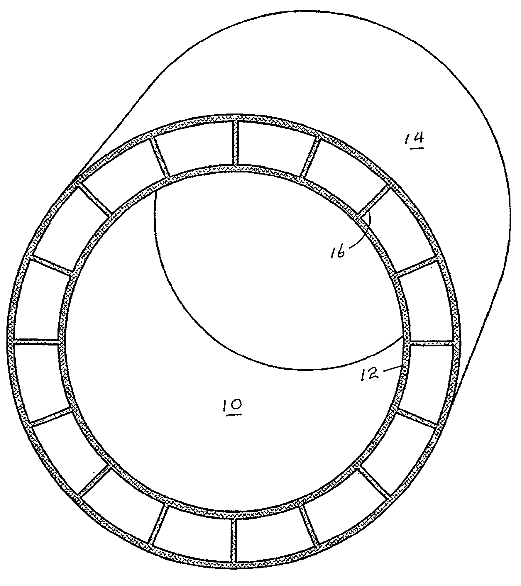
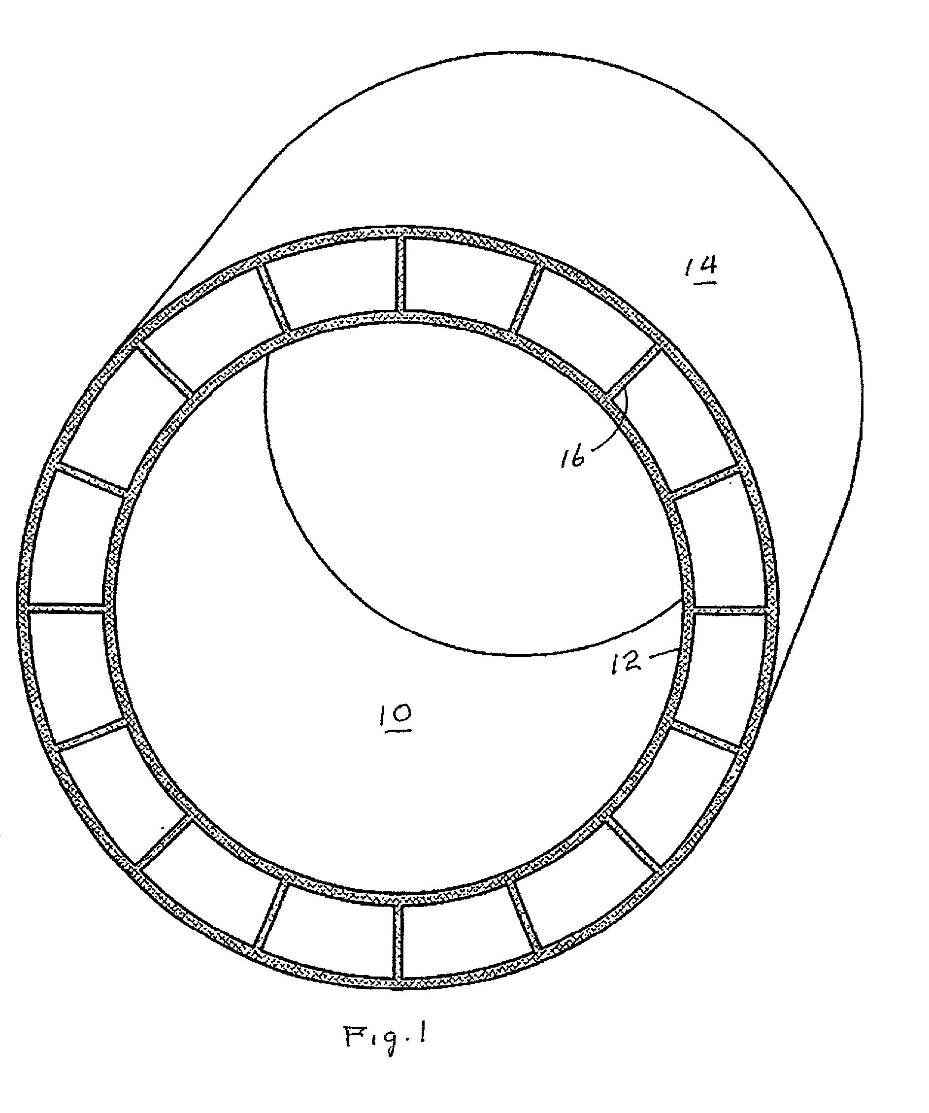
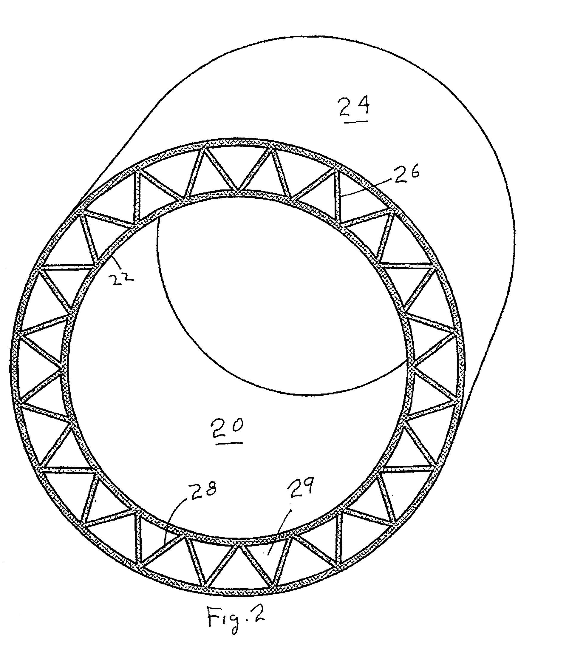
[0047] Reference will now be made to the drawing, wherein like parts have been given like reference numbers. Referring to FIG. 1, a composite tube 10 according to this invention is made up of an inner tube 12, an outer tube 14 and a plurality of ribs 16 therebetween. Referring to FIG. 2, a modified composite tube 20 of this invention is made up of an inner tube 22, and outer tube 24, a set of "left handed" "off radial" ribs 26 and an alternating set of right handed "off-radial" ribs 28. Note that the combination of the inner tube, the outer tube and the two sets of ribs forms generally triangular truss cells 29. Referring to FIG. 4, a further modified composite tube 40 of this invention is made up of an inner tube 42, an outer tube 44, and a series of left and right handed alternating off-radial ribs 46 and 48, respectively. Note that the left and right handed ribs contact and are joined to the inner and outer tubes, respectively, out of contact with each other. This is to be compar...


PUM

PropertyMeasurementUnit
axial lengthaaaaaaaaaa
angleaaaaaaaaaa
anglesaaaaaaaaaa

Abstract

An elongated composite tube made up of an inner tube 42 and an outer tube 44 (see FIG. 3) with a plurality of elongated helical ribs disposed between the inner tube and the outer tube in a supporting relationship to both. A slinky like toy made from the composite tube is also disclosed, as is a method of making both.

Description

GENERAL FIELD OF THE INVENTION[0001] This invention relates to generally tubular articles such as cores for rolled goods like carpets and plastic film. It more particularly refers to such cores that are light in weight and have unusually high crush resistance. It further relates to decorative toy articles made from such tubular articles.BACKGROUND OF THE INVENTION[0002] Cores for all kinds of rolled goods, such as plastic film, carpeting, paper products, and the like, are well known. In many instances, these cores are simply hollow cylindrical rolls of cardboard or other materials. In other cases, these cores may be solid plastic, wood or metal rods.[0003] In one very old patent, U.S. Pat. No. 3,627,221, there is described a decorative end plug for rolled paper, such as newsprint. The end plug is made up of a centrally located opening for receiving an axially disposed shaft, a generally flat, solid, disc like portion 16 disposed radially about the shaft receiving axial opening 18, a...

Claims


Application Information

Patent Timeline
Patent Type & Authority Applications(United States)
IPC IPC(8): B29C48/11B29C48/13B29C48/32B29C48/355B29C53/14F16L9/19
CPCB29C47/0023B29C47/24B29C47/003B29C47/0033B29C47/0038B29C47/005B29C47/0057B29C47/0066B29C47/065B29C47/34B29C53/14B29L2023/00B29L2023/22B29L2024/006B29L2031/60B29L2031/704B29L2031/7732F16L9/19Y10T428/139B29C47/0028B29C48/09B29C48/11B29C48/12B29C48/13B29C48/001B29C48/0015B29C48/0018B29C48/0022B29C48/21B29C48/33B29C48/355
Inventor HERRINGTON, F. JOHN
Owner PROTEUS
Why Eureka
Try Eureka