
Rotor shield for magnetic rotary machine

a magnetic rotary machine and shield technology, applied in the direction of magnetic circuit rotating parts, mechanical energy handling, shape/form/construction, etc., can solve the problems of rotors being subject to eddy current losses, reduce eddy current losses, the effect of reducing eddy current losses

Inactive Publication Date: 2002-09-12
CAPSTONE TURBINE
View PDF10 Cites 60 Cited by
  • Summary
  • Abstract
  • Description
  • Claims
  • Application Information

AI Technical Summary

Benefits of technology

[0012] In another aspect of the invention, a method for reducing eddy current losses in a permanent magnet rotor is described wherein the method includes (1) providing a permanent magnet stator; (2) providing a permanent magnet rotor designed to rotate about an axis disposed within said stator, said rotor including a permanent magnet, an electrically conductive nonmagnetic shield and a sleeve, wherein said shield has portions positioned inside said sleeve; and (3) rotating said permanent magnet rotor such that said shield reduces said eddy current losses.
[0013] In another aspect of the invention, a method includes (1) providing a cylindrical permanent magnet having a cylindrical permanent magnet outer surface; (2) providing an annular shield having an inner annular surface in contact with said cylindrical permanent magnet outer surface, said annular shield having an annular shield outer surface; (3) providing an annular sleeve having an annular sleeve inner surface in contact with said annular shield outer surface, wherein resistivity of said shield is lower than resistivity of said sleeve; and (4) generating eddy currents in said shield such that said eddy current losses are reduced.

Problems solved by technology

The rotor may be subject to eddy current losses caused by magnetic field harmonics.

Method used


Image

  • Rotor shield for magnetic rotary machine
  • Rotor shield for magnetic rotary machine
  • Rotor shield for magnetic rotary machine

Examples


Embodiment Construction

[0032] Referring now to the drawings, like reference numerals designate identical or corresponding parts throughout the several views.

[0033] Mechanical Structural Embodiment of a Turbogenerator

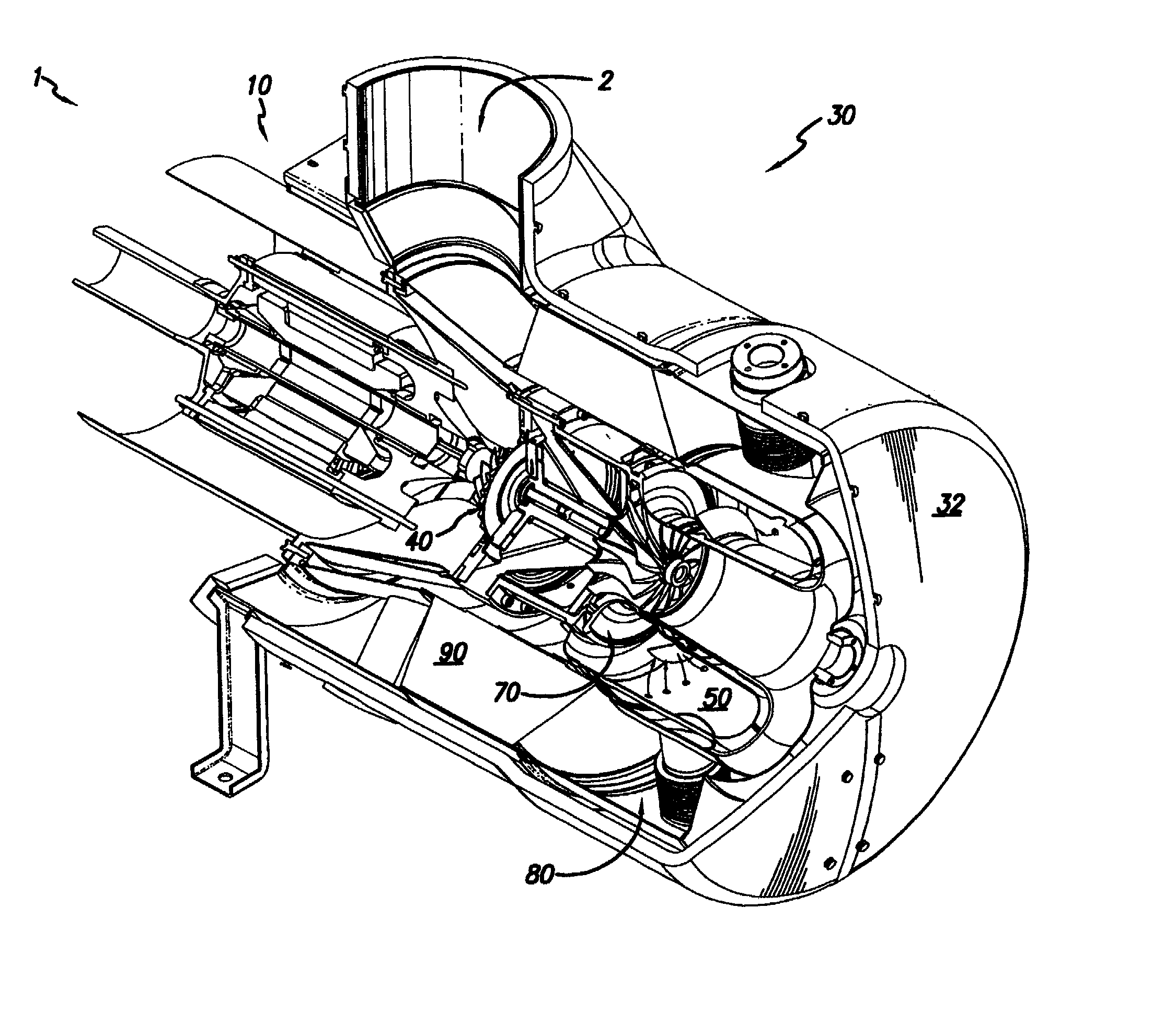
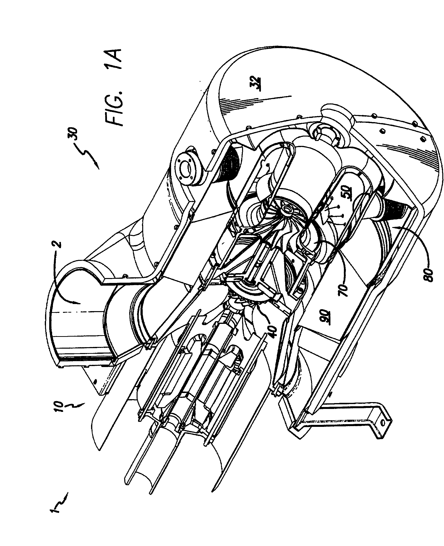
[0034] With reference to FIG. 1A, an integrated turbogenerator 1 according to the present invention generally includes motor / generator section 10 and compressor-combustor section 30. Compressor-combustor section 30 includes exterior can 32, compressor 40, combustor 50 and turbine 70. A recuperator 90 may be optionally included.

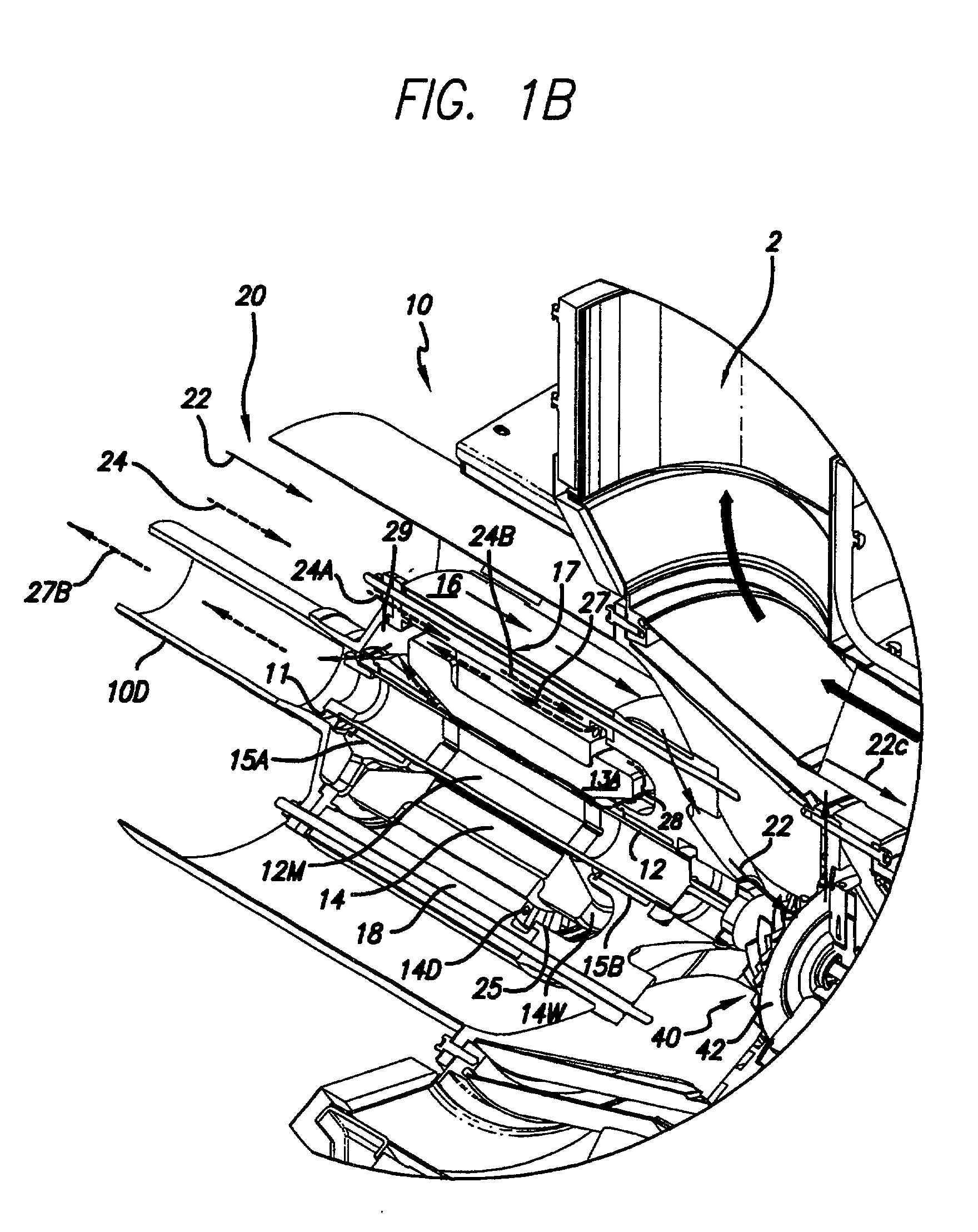
[0035] Referring now to FIG. 1B and FIG. 1C, in an embodiment of the present disclosure, motor / generator section 10 may be a permanent magnet motor generator having a permanent magnet rotor or sleeve 12. Throughout the present disclosure rotor or sleeve 12 is referred to as a permanent magnet rotor, any suitable rotor technology may be used including wound rotors. Permanent magnet rotor or sleeve 12 may contain a permanent magnet 12M. Permanent magnet rotor or sleeve 12 ...


PUM


Abstract

A magnet machine includes a magnet rotor. The rotor includes a sleeve and a magnet. The magnet is positioned within the sleeve. A highly electrically conductive, nonmagnetic shield surrounds the magnet. The shield reduces rotor eddy current losses and lowers rotor operating temperature, thereby improving efficiency of the machine.

Description

CROSS REFERENCE TO RELATED APPLICATIONS[0001] This patent application claims the priority of provisional patent application serial No. 60 / 245,697, filed Nov. 2, 2000, and serial No. 60 / 246,380 filed Nov. 7, 2000.BACKGROUND OF THE INVENTION[0002] 1. Field of the Invention[0003] The present invention relates generally to magnetic rotary machines. More particularly, the invention relates to a rotor system for limiting eddy current losses and lowering operating temperature.[0004] 2. Discussion of the Background[0005] Magnetic rotary machines include a stator with a rotatable rotor positioned therein and supported by bearings.[0006] The rotor may be subject to eddy current losses caused by magnetic field harmonics. The term eddy current losses means heat generated by eddy currents. Magnetic field harmonics are oscillations in the magnetic field at any frequency other than the fundamental frequency. The term "winding harmonics" means magnetic field harmonics caused by stator windings. The...

Claims


Application Information

Patent Timeline
IPC IPC(8): H02K1/27H02K11/00
CPCH02K1/2733H02K11/01H02K7/183H02K11/012Y02E10/72
Inventor QIN, DINYUSTEWART, MATTHEWSTAHL, DAVID A.
Owner CAPSTONE TURBINE
Learn More