Bounded power supply voltage positioning

a power supply and positioning technology, applied in the field of electrical power supplies, can solve the problems of reducing the basic geometries of semiconductor devices or elements, reducing the size of high-performance integrated circuits, and seeing an almost stunning rate of device complexity and sophistication, so as to facilitate active voltage positioning, minimize voltage overshoot, and save operating power

Inactive Publication Date: 2002-09-12
SEMTECH CORP
View PDF0 Cites 64 Cited by
  • Summary
  • Abstract
  • Description
  • Claims
  • Application Information

AI Technical Summary

Benefits of technology

0006] An apparatus and method provide bounded voltage droop, which facilitates active voltage positioning in power supply applications. A bounded droop circuit generates a droop voltage based on load current, such that the output voltage provided to the load by an associated power supply drops below its nominal value by an amount determined by the droop voltage. The droop circuit includes a droop limiter that establishes a maximum droop voltage that is independent of load current, thereby preventing the output voltage from dropping below a minimum operating voltage of the load.
0007] Because the droop limiting function establishes an accurate maximum droop voltage, the bounding limit may be set substantially at the lower operating limit of the load, thereby allowing the power supply to take full advantage of the load's operati...

Problems solved by technology

In tracing the pace of development for digital electronics, one sees an almost stunning rate of increase in device complexity and sophistication.
Both electrical and economic constraints limit the size of high-performance integrated circuits, and so chip designers continually shrink the basic geometries of the semiconductor devices or elements comprising thes...

Method used


Image

  • Bounded power supply voltage positioning
  • Bounded power supply voltage positioning
  • Bounded power supply voltage positioning

Examples


Embodiment Construction

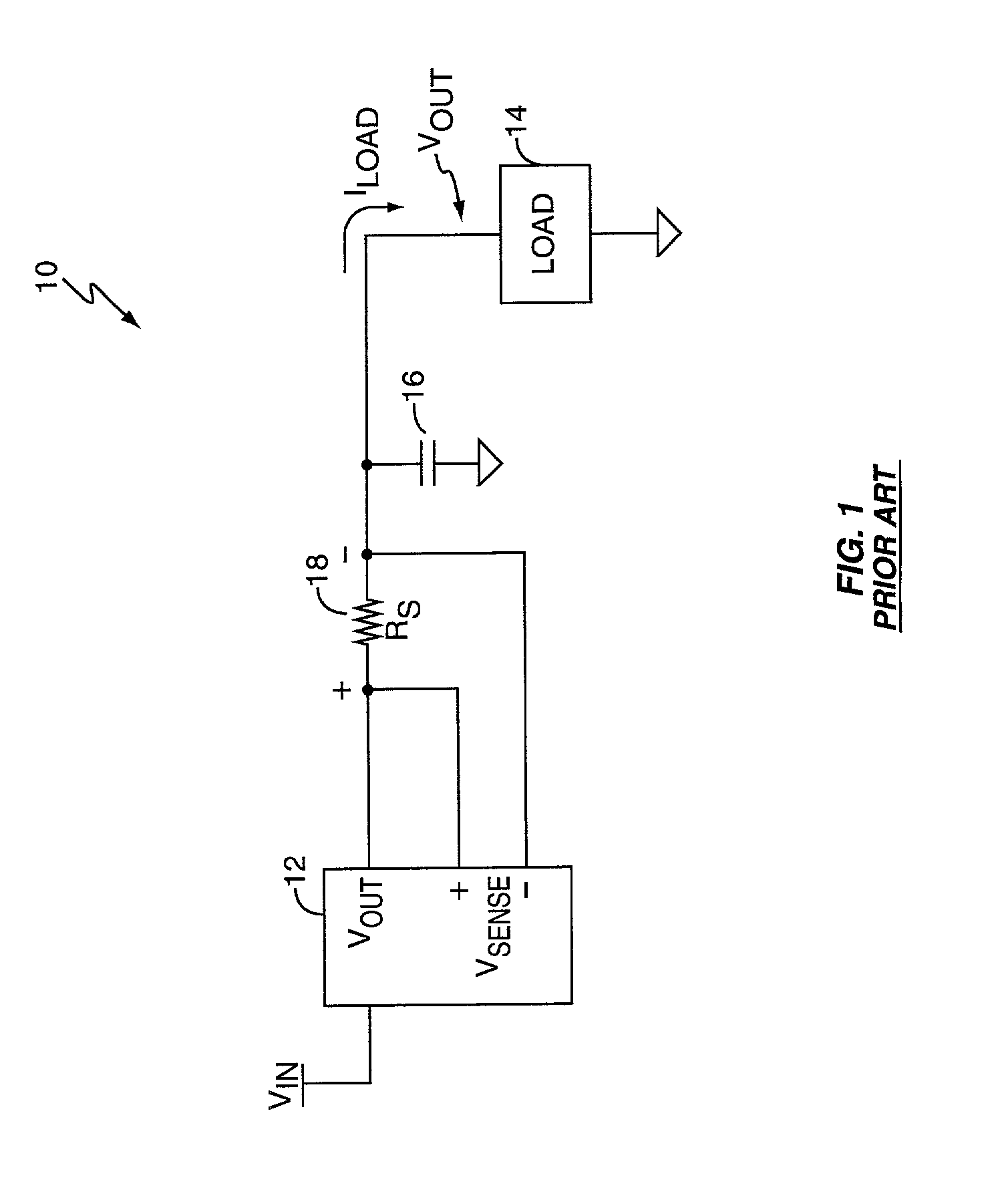
[0020] FIG. 1 is a diagram of a typical electrical circuit 10 comprising a power supply 12 providing a regulated voltage signal V.sub.OUT to a load 14. One or more output capacitors 16 sit in parallel with the load 14 and provide it with input filtering and local charge storage. The supply 12 sources load current through a sense resistor 18 that provides a differential voltage V.sub.SENSE proportional to load current. The supply 12 uses the sense voltage V.sub.SENSE to implement active voltage positioning for the load 14 for purposes explained below.

[0021] The load 14 may, for example, be a microprocessor or other logic circuit that requires the supply 12 to respond to fast changes in required load current I.sub.LOAD. A typical step-change in load current I.sub.OUT for a microprocessor-based load 14 might be an increase from less than half an Amp to more than twenty Amps in less than a hundred microseconds. Conversely, a microprocessor-based load 14 might rapidly change from drawing...


PUM


Abstract

A voltage positioning technique allows a power supply controller to more fully exploit active voltage positioning as a way of maintaining supply voltage within the limits defined for an associated electrical load. The supply voltage is allowed to "droop" as a function of load current. Droop may be implemented in linear proportion to load current, or as a discrete droop function once load current exceeds a given threshold. In either case, the droop circuitry of the supply controller implements a bounding function that establishes an accurately known maximum droop voltage magnitude. This maximum droop voltage limit establishes a reliable lower limit for the supply voltage independent of increasing load current. This accurately set lower bound for the droop voltage enables the controller to more aggressively position the supply voltage at the lower voltage limit of the load, which minimizes voltage overshoot and load power consumption.

Description

BACKGROUND OF THE INVENTION[0001] The present invention generally relates to electrical power supplies, and particularly relates to output voltage positioning control.[0002] Electronic devices of all types are an integral part of everyday life. While the purposes served by these devices is widely varied, from cell phones to GPS receivers, to portable or desktop computers, the devices themselves have several characteristics in common. For example, with the increasing sophistication of the average consumer and the competitive market pressure attendant with that sophistication, the capabilities and features of modern electronics advances at a relentless pace. Advances in device capability or speed generally arise from building in more powerful computational systems at the core of these electronic devices.[0003] At the heart of these computational cores are advanced microprocessors or other digital logic devices. In tracing the pace of development for digital electronics, one sees an al...

Claims


Application Information

Patent Timeline
IPC IPC(8): H02M3/156H02M3/158
CPCH02M3/156H02M3/158H02M2001/0025H02M1/0025
Inventor GROOM, TERRY J.PULLEN, STUART
Owner SEMTECH CORP
Why Eureka
Try Eureka