

Three-phase current transformer
a current transformer and three-phase technology, applied in the field of current transformers, can solve the problems of large magnetic influence imparted to the coils of the other phases, and achieve the effect of simplifying the structur
- Summary
- Abstract
- Description
- Claims
- Application Information
AI Technical Summary
Benefits of technology
Problems solved by technology
Method used
Image

Examples
first embodiment
[0022] First Embodiment
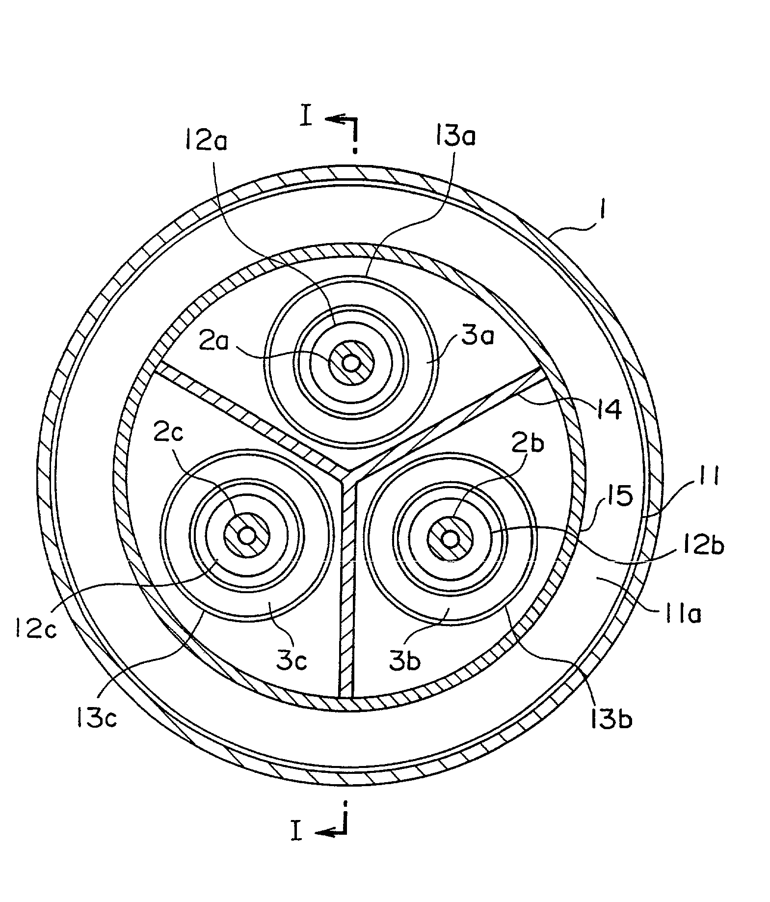
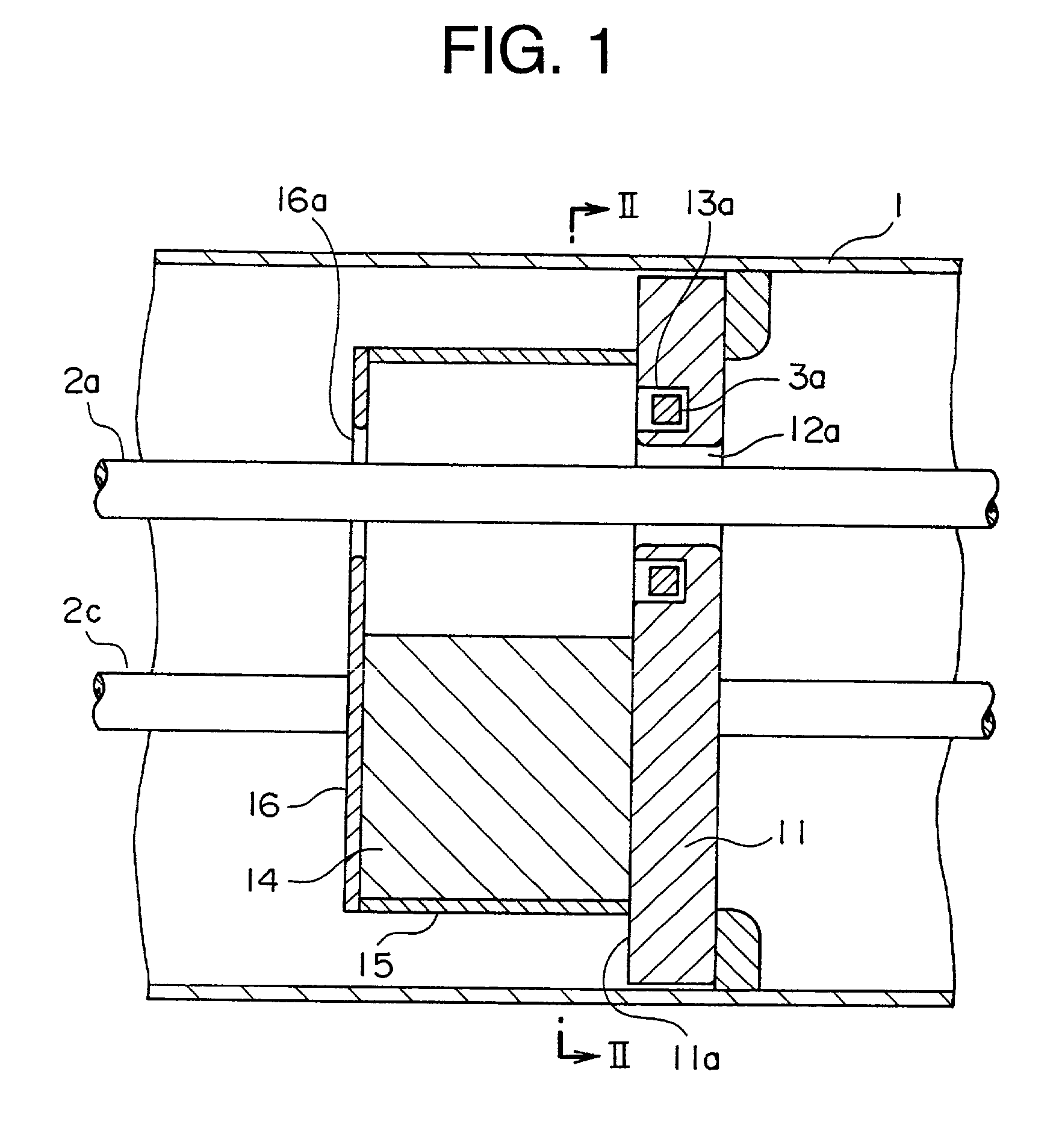
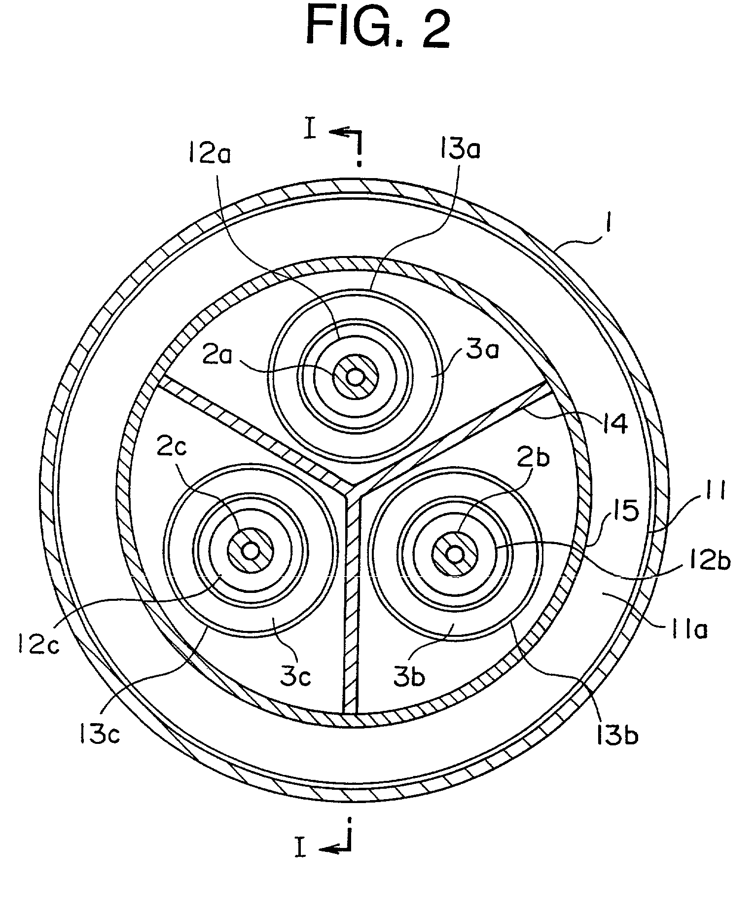
[0023] FIG. 1 is a cross-sectional view of a three-phase package type current transformer in accordance with a first embodiment of the present invention, and FIG. 2 is a cross-sectional view taken along a line II-II of FIG. 1. FIG. 1 is a cross-sectional view taken along a line I-I of FIG. 2.
[0024] In the figures, three conductors 2a to 2c are received within a cylindrical pressure vessel 1 that is filled with SF6 gas, an insulating and arc-extinguishing gas. Three-phase conductor is comprised of the conductors 2a to 2c. Also, a plate-like (disc-like) metal adaptor 11 is fixed to the interior of the pressure vessel 1. The metal adaptor 11 has first to third conductor through-holes 12a to 12c into which the conductors 2a to 2c are inserted.
[0025] Also, the metal adaptor 11 has a coil insertion surface 11a which is parallel with planes orthogonal to the conductors 2a to 2c. First to third annular coil insertion slots 13a to 13c are formed in the peripheries of t...
second embodiment
[0036] Second Embodiment
[0037] FIG. 3 is a front view showing a three-phase package type current transformer in accordance with a second embodiment of the present invention, and FIG. 4 is a partially-sectional side view showing the three-phase package type current transformer of FIG. 3. In the figures, a metal adaptor 20 is fixed to the interior of the pressure vessel 1 shown in FIG. 1. The metal adaptor 20 has first to third metal plates 21 to 23.
[0038] The positions of the first to third metal plates 21 to 23 are displaced from each other in the longitudinal direction of the conductors 2a to 2c, and the first to third metal plates 21 to 23 are partially bonded to each other at their end surfaces in the longitudinal direction of the conductors 2a to 2c so as to be integrated with each other.
[0039] The first metal plate 21 has a first conductor through hole 21a and an annular first coil insertion slot 21b. A second conductor through-hole 22a and an annular second coil insertion slot...
third embodiment
[0045] Third Embodiment
[0046] Next, FIG. 5 is a front view showing a three-phase package type current transformer in accordance with a third embodiment of the present invention. In the figure, a three-phase package type plate-like (disc-like) insulating spacer 31 made of an insulator is fixed in the interior of the pressure vessel 1 shown in FIG. 1. The conductors 2a to 2c are supported by the insulating spacer 31 while being electrically insulated with respect to the pressure vessel 1.
[0047] The insulating spacer 31 has first to third conductor through-holes 32a to 32c through which the conductors 2a to 2c are inserted, and first to third annular spacer slots 33a to 33c formed in the periphery of the first to third conductor through-holes 32a to 32c, respectively. The first to third Rogowskii coils 3a to 3c are disposed within the first to third spacer slots 33a to 33c so as to be spaced from the inner wall surfaces of the first to third spacer slots 33a to 33c, respectively.
[0048]...
PUM
| Property | Measurement | Unit |
|---|---|---|
| current | aaaaa | aaaaa |
| sectional area | aaaaa | aaaaa |
| degree of electric power | aaaaa | aaaaa |
Abstract
Description
Claims
Application Information