Brent waveguide for connection to at least one device, adaptive passive alignment features facilitating the connection and associated methods

a waveguide and passive alignment technology, applied in the field of bent waveguides, can solve the problems of ineffective transceivers, misalignment of optical paths, and affecting so as to reduce the possibility of physical damage, increase design flexibility, and ensure the reliability of optical connections

Inactive Publication Date: 2002-09-12
THE WHITAKER CORP
View PDF0 Cites 9 Cited by
  • Summary
  • Abstract
  • Description
  • Claims
  • Application Information

AI Technical Summary

Benefits of technology

0009] The concepts of the present application overcome substantial disadvantages of the conventional connection to devices for transmitting and/or receiving optical signals. It is an object of the invention to make the optical

Problems solved by technology

However, vibration and temperature changes can alter the alignment between the transmitter, receiver, connector, and bulk optics.
Additionally, any inconsistencies in positioning arising during the manufacturing and integration process can result in misalignment of the optical path.
Either of these sources of misalignment will render the transceiver ineffective.
Such a solution is effective for systems incorporating a single transmit chip or a single receive chip, but is not effective

Method used


Image

  • Brent waveguide for connection to at least one device, adaptive passive alignment features facilitating the connection and associated methods
  • Brent waveguide for connection to at least one device, adaptive passive alignment features facilitating the connection and associated methods
  • Brent waveguide for connection to at least one device, adaptive passive alignment features facilitating the connection and associated methods

Examples


Embodiment Construction

[0038] The exemplary embodiments of the invention claimed and the appended claims may be more fully appreciated by reference to the following description of preferred embodiments. Within the drawing figures, it should be understood that like elements are identified by like reference numbers.

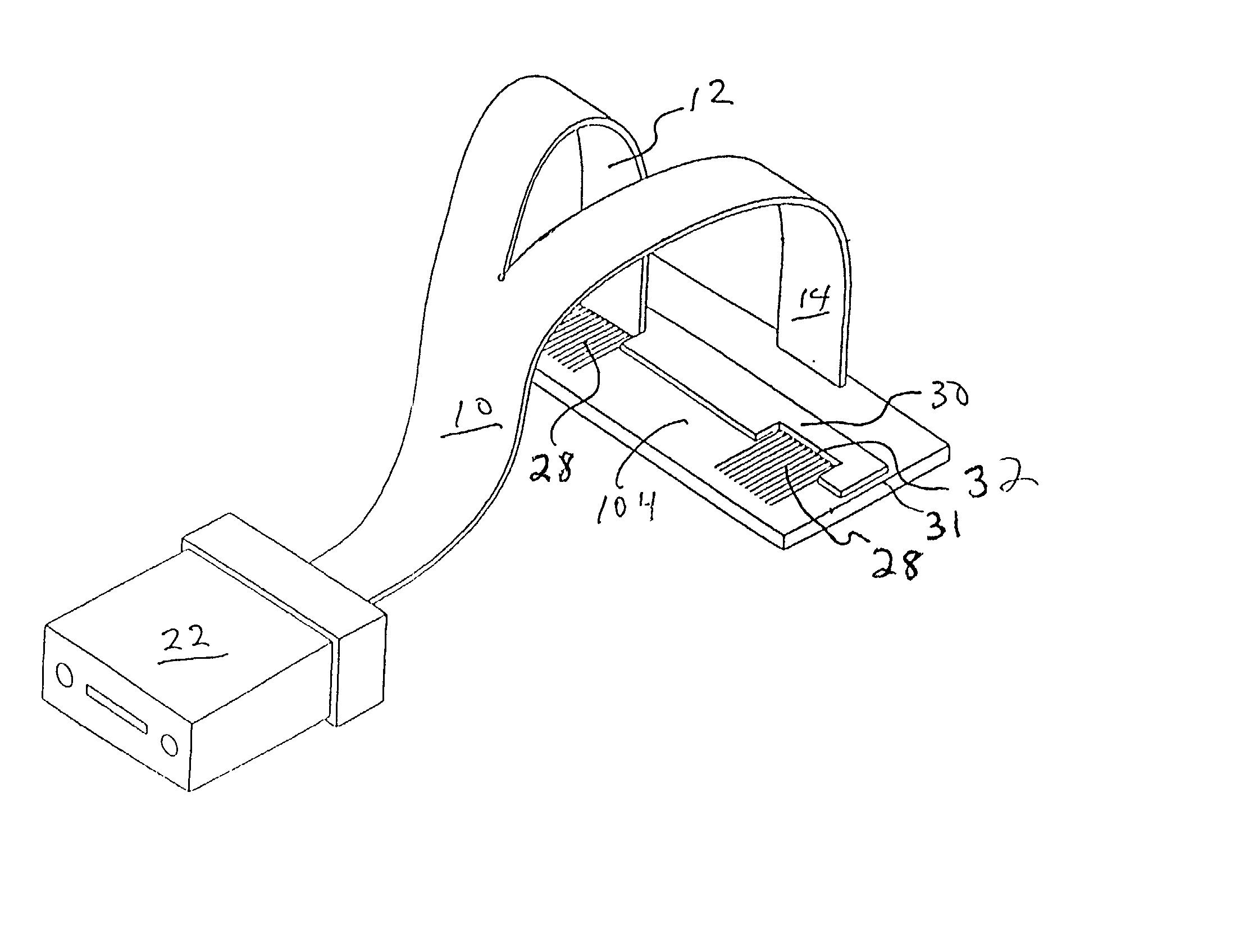
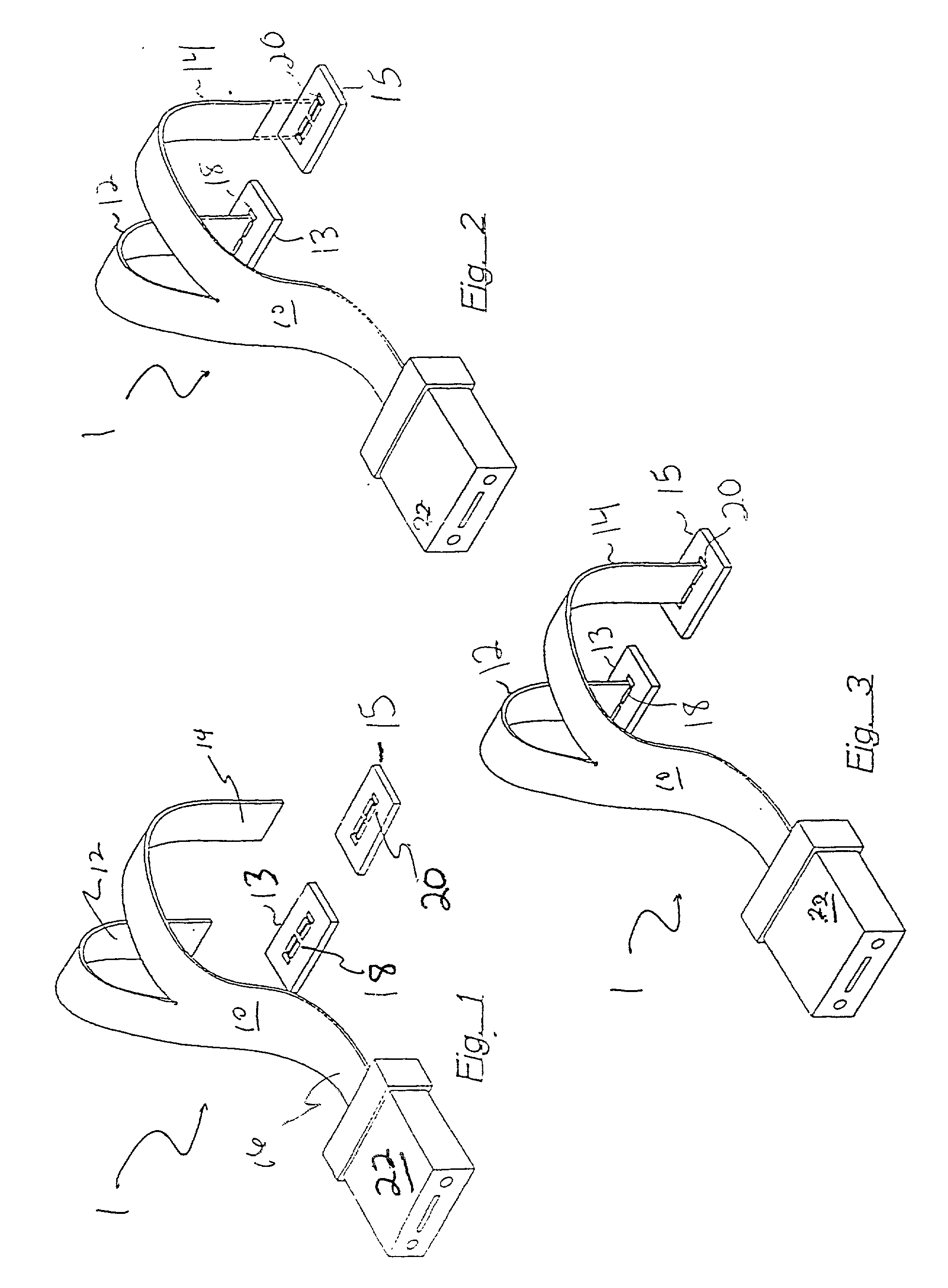
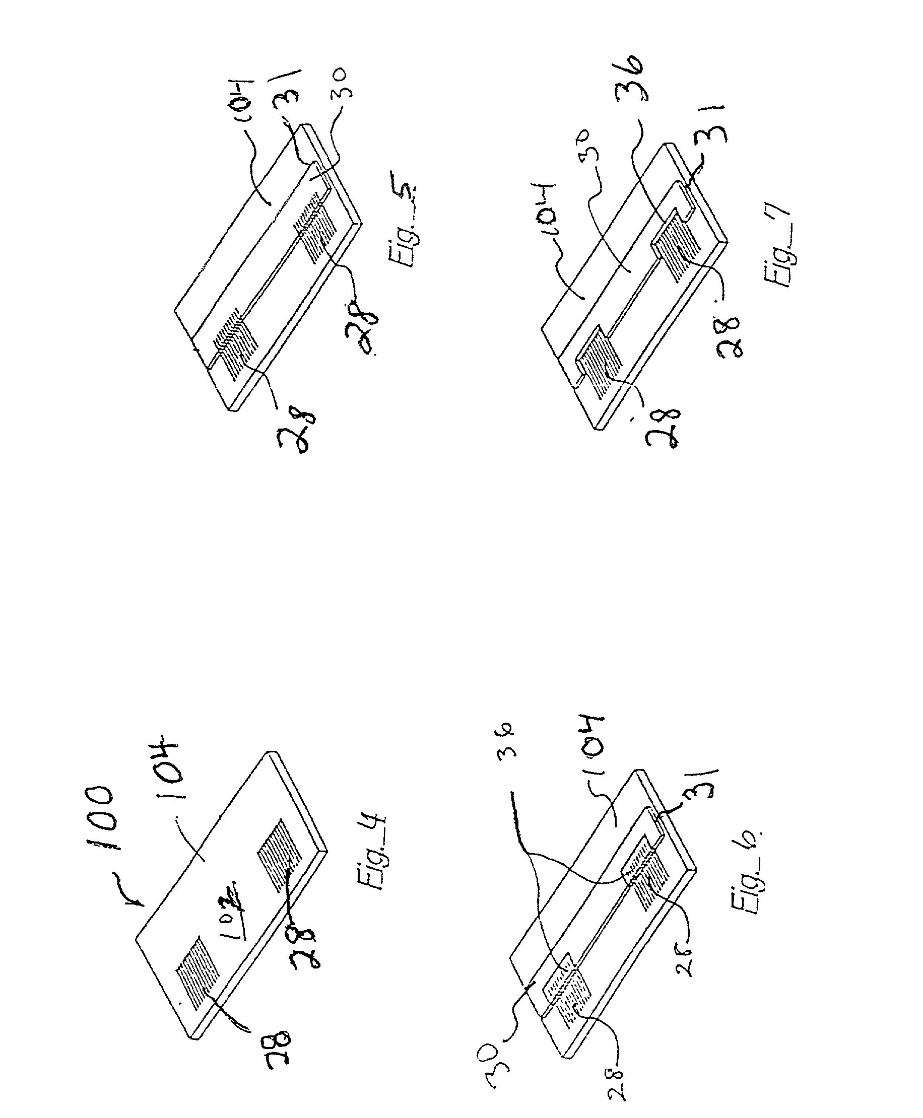
[0039] As an example of a configuration in accordance with the present invention, a flexible optical waveguide having at least three arms to connect both transmitter and receiver signals, e.g., to a single connector, such as a ferrule, will be described below. Arms other than that to the connector must be independently aligned and connected to both arrays.

[0040] The two arms to the transceiver are bent out of the plane of the connector and / or of the devices. This bend gives these individual arms the flexibility needed to independently align the two arms, one to the transmitter (Tx) array and one to the receiver (Rx) array. This bend also eliminates the need for a mirror to supply light from the T...


PUM


Abstract

A bent, flexible optical waveguide is attached to a device which receives or transmits optical signals. The bend of the flexible waveguide allows the relative positioning of the device to be in a different plane than an opposite end of the waveguide and is robust under a variety of environmental stresses. When used with two or more devices, e.g., a transceiver having both a transmitter array and a receiver array, the bend of the flexible waveguide allows the separate ends of the waveguide to be adaptively aligned independently. An alignment feature created adjacent to the device in accordance with the position of the device is used to passively align the tips of the waveguide to the module. The alignment feature can be of any shape that allows them to abut and hold the end of the waveguide, including cylinders, cutout regions of a transparent layer, and slots in or between the pedestals. The optical waveguide bends the direction of the light propagating within the waveguide to allow communication between the device and a component attached to the opposite end of the waveguide.

Description

CROSS-REFERENCE TO RELATED APPLICATIONS[0001] This application claims priority under 35 U.S.C. .sctn.119 to Provisional Application Serial No. 60 / 068,100 filed Dec. 19, 1997, which is hereby incorporated by reference in its entirety for all purposes.BACKGROUND OF THE INVENTION[0002] 1. Field of the Invention[0003] The present application is directed to using a bent waveguide to connect to at least one device for transmitting or receiving optical signals, especially when constructing connectorized transceiver modules. The bend of the flexible waveguide allows the relative positioning of the device to be in a different plane than an opposite end of the waveguide and is robust under a variety of environmental stresses. In particular, a flexible waveguide having separate arms is used to connect two or more devices, e.g., a laser transmitter array and a receiver detector array, typically to a connector. The separate arms allow the ends of the waveguide to be adaptively, passively aligned...

Claims


Application Information

Patent Timeline
IPC IPC(8): G02B6/42G02B6/43
CPCG02B6/423G02B6/4246G02B6/4249G02B6/4292G02B6/43G02B6/4259G02B6/4242
Inventor KADAR-KALLEN, MICHAEL AARONROWLETTE, JOH ROBERT SR.GREEN, ERIC
Owner THE WHITAKER CORP
Why Eureka
Try Eureka