
Hybridization device

Inactive Publication Date: 2002-09-12
HITACHI SOFTWARE ENG
View PDF1 Cites 7 Cited by
  • Summary
  • Abstract
  • Description
  • Claims
  • Application Information

AI Technical Summary

Benefits of technology

[0013] By making the sheet from a material that has affinity with the substrate, the sheet and the substrate can adhere to each other to enhance sealing for enclosing the sample solution.
[0015] The above-described sheet may be slightly larger than the substrate so that the corner of the sheet can easily be pinched.

Problems solved by technology

However, since the cover glass is extremely thin and light, placing and fixing the cover glass on the sample solution at a predetermined position of the slide glass requires certain experience and technique.
In the worst case, the glass cover may be broken and the precious sample may be wasted.
As a result, the component contained in the solution remaining after the evaporation of the sample solution is hard to wash off and likely to stay on the glass slide, resulting as noise upon analysis.

Method used


Image

  • Hybridization device
  • Hybridization device
  • Hybridization device

Examples


embodiment 1

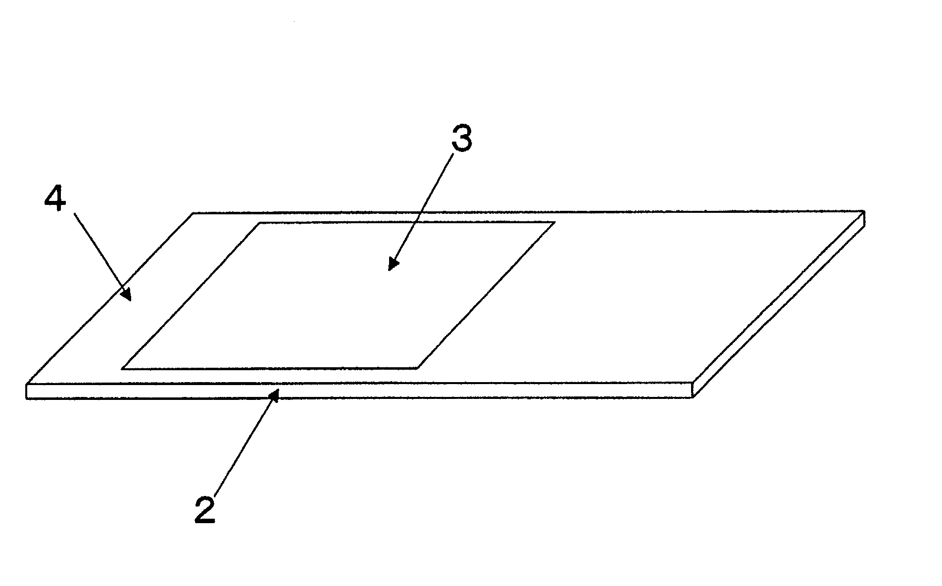
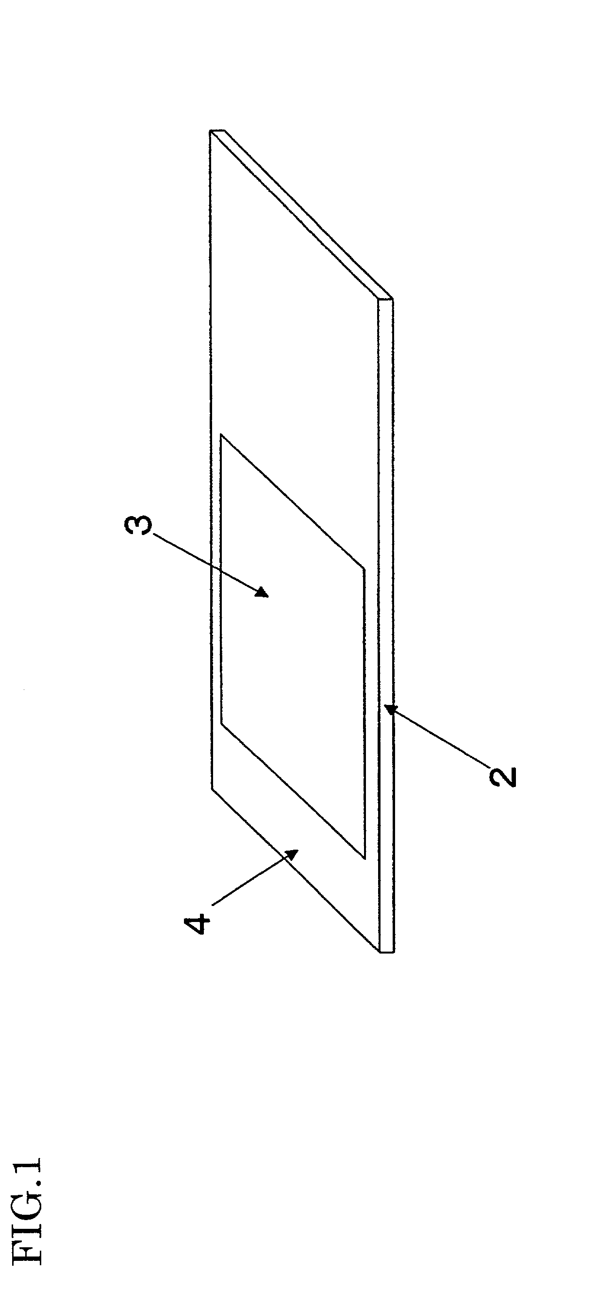
[0025] FIG. 1 is a schematic view showing a structure of a hybridization device according Embodiment 1 of the present invention. A silicone-rubber-based sheet 2 has a hydrophilic region 3 and a hydrophobic region 4. The hydrophilic region 3 is a region that faces a DNA-fixed (generally biopolymer-fixed) region of a substrate (not shown) and the hydrophobic region 4 is a surface region of the sheet 2 surrounding the hydrophilic region 3. The thickness of the sheet 2 is about 1 mm. The substrate on which the probe biopolymers are fixed is made of glass, plastic, metal or the like. The dimensions of the slide glass commonly used as the substrate is 76.times.26 mm.sup.2 according to the Japanese standard, 3.times.1 inch.sup.2 (25.4 mm.sup.2) according to the American standard, and 25.times.75 mm.sup.2 according to the European standard. Silicone rubber is generally hydrophobic and glass is hydrophilic.

[0026] By way of example, a method for performing hybridization reaction using the sil...

embodiment 2

[0038] Since the hollow 6 is formed , a larger amount of sample solution can be enclosed, which is preferable for a long-time hybridization reaction.

embodiment 3

[0039] FIG. 5 is a schematic view showing a structure of a hybridization device according to According to this embodiment, a silicone-rubber-based sheet 8 has a plurality of hollows 9 on its surface corresponding to DNA-fixed (generally biopolymer-fixed) regions of a plurality of slide glasses. The surfaces of the hollows 9 are made hydrophilic. The region surrounding the hollows 9 remains hydrophobic as a hydrophobic region 10.

[0040] According to Embodiment 3, hybridization reaction can be carried out for a plurality of slide glasses by using the sheet 8, thereby simplifying manipulation.

[0041] The present invention is not limited to the above-described embodiments.

[0042] The present invention also contemplates a hybridization device comprising a combination of a slide glass fixed with probe biopolymers and the above-described sheet.

[0043] Instead of using a photocatalist semiconductor material, the hydrophilic property can be achieved by applying a hydrophilic coating.

[0044] The ...


PUM

PropertyMeasurementUnit
Timeaaaaaaaaaa
Hydrophilicityaaaaaaaaaa
Affinityaaaaaaaaaa

Abstract

The present invention has an objective of providing a hybridization device which anyone can easily and steadily set up, and with which evaporation of a sample solution can be minimized. A silicone-rubber-based sheet 2 has a hydrophilic region 3 and a hydrophobic region 4 surrounding the hydrophilic region 3, the hydrophilic region 3 corresponding to a region of a substrate (not shown) where DNA is fixed. Accordingly, hybridization reaction that takes long time can be carried out stably with a small amount of sample solution even without a sealing case or water for preventing the sample solution from evaporating.

Description

PRIORITY INFORMATION[0001] This application claims priority to Japanese Application Serial No. 2001-62418, filed Mar. 6, 2001.BACKGROUND OF THE INVENTION[0002] The present invention relates to a hybridization device for determining the presence or absence of a sequence of interest in a sample biopolymer through hybridization reaction between the sample biopolymer and a probe biopolymer.[0003] Conventionally, hybridization methods that use nucleic acids or proteins with known sequences as probes are often employed in order to identify and / or fractionate a molecular in an organism, particularly in order to detect DNA of interest or the presence of genetic DNA. Specifically, a DNA chip is used which is a slide glass on which probe DNAs are fixed. First, a solution containing fluorescence-labeled sample DNA is dropped on the slide glass having probe DNAs fixed thereon. Then, the slide glass is covered with a cover glass to allow hybridization reaction. The sample DNA that binds to the p...

Claims


Application Information

Patent Timeline
IPC IPC(8): B01L3/00C12M1/34C12M1/00C12Q1/68
CPCB01L3/5085B01L3/5088B01L2300/0636B01L2300/0822
Inventor SATO, KEIICHIMORITA, TOSHIKI
Owner HITACHI SOFTWARE ENG
Learn More