Configurable switchgear system

Inactive Publication Date: 2002-09-12
KOHLER CO
View PDF0 Cites 40 Cited by
  • Summary
  • Abstract
  • Description
  • Claims
  • Application Information

AI Technical Summary

Benefits of technology

0011] The present inventors have discovered that it is possible to design a flexible, configurable switchgear system that can operate in a variety of modes, perform a variety of different types of transfers and other switching operations, and operate both in response to and independently of commands or information from outside sources. To allow for maximum flexibility, the switchgear system is at least partly implemented using software that includes the necessary programming and related information for allowing the switchgear system to operate in such a variety of modes and manners. To guarantee that the switchgear system operates in the proper mode and performs the proper transfers or other switching operations for a given operational situation, the configurable switchgear system further includes an operator interface by which the operator must provide specific information to access and enable the proper mode and switching operations. In the preferred embodiment of the invention, the operator interface includes a port at which a plug-in card or cartridge storing the necessary information can be inserted.
0012] More particularly, the present invention relates to a switchgear system. The switchgear system includes a first switch capable of electrically coupling a first power source and a load, and a second switch capable of electrically coupling a second power source and the load. The switchgear system further includes a control unit coupled to both the first and second switches. The control unit includes a memory that stores software, and the control unit is capable of operating in at least two modes and controlling opening and closing of the first and second switches in accordance with those modes based upon the software. The switchgear system additionally includes an operator interface coupled to the control unit. The operator interface is capable of receiving additional information that enables the operation of the control unit in at least one of the at least two modes.
0013] The present invention further

Problems solved by technology

Not all switchgear systems allow the direct coupling of a customer power source to the utility power grid.
This basic mode of transfer of the load(the "open transition transfer"), however, is typically undesirable insofar as there is at least a short period of time in which no power source is providing power to the load.
Further, switchgear systems that are only configured to perform open transition transfers do not have the capability of coupling the customer power source to the power grid for the purpose of providing power to the power grid.
However, in order to provide for closed transition or soft load transfers, the complexity of the design of a switchgear system becomes greatly increased.
In addition to the complexity associated with performing closed transition or soft load transfers, modern switchgear systems are further complicated because the switchgear systems are often designed to perform switching transfers (or to otherwise change the switching status of the circuit breakers) only under certain specified conditions.
Designing a switchgear system to operate in any one of these modes of operation, or in response to different commands or other information, further increases the complexity of the switchgear system.
Although conventional switchgear systems do exist for performing each of the above-described types of functions, such conventional switchgear systems are typically hardwired and custom-designed for use with specific respective customer power sources, loads and applications, and each such switchgear system is typically restricted to performing a particular respective type of transfer or other switching operation, and to operating in a particular respective mode.
That is, conventional switchgear systems, due to their being hardwired and custom-designed, are inflexible in terms of the degree to which their operation can be varied to more appropriately fit changing operational circumstances.

Method used


Image

  • Configurable switchgear system
  • Configurable switchgear system
  • Configurable switchgear system

Examples


Embodiment Construction

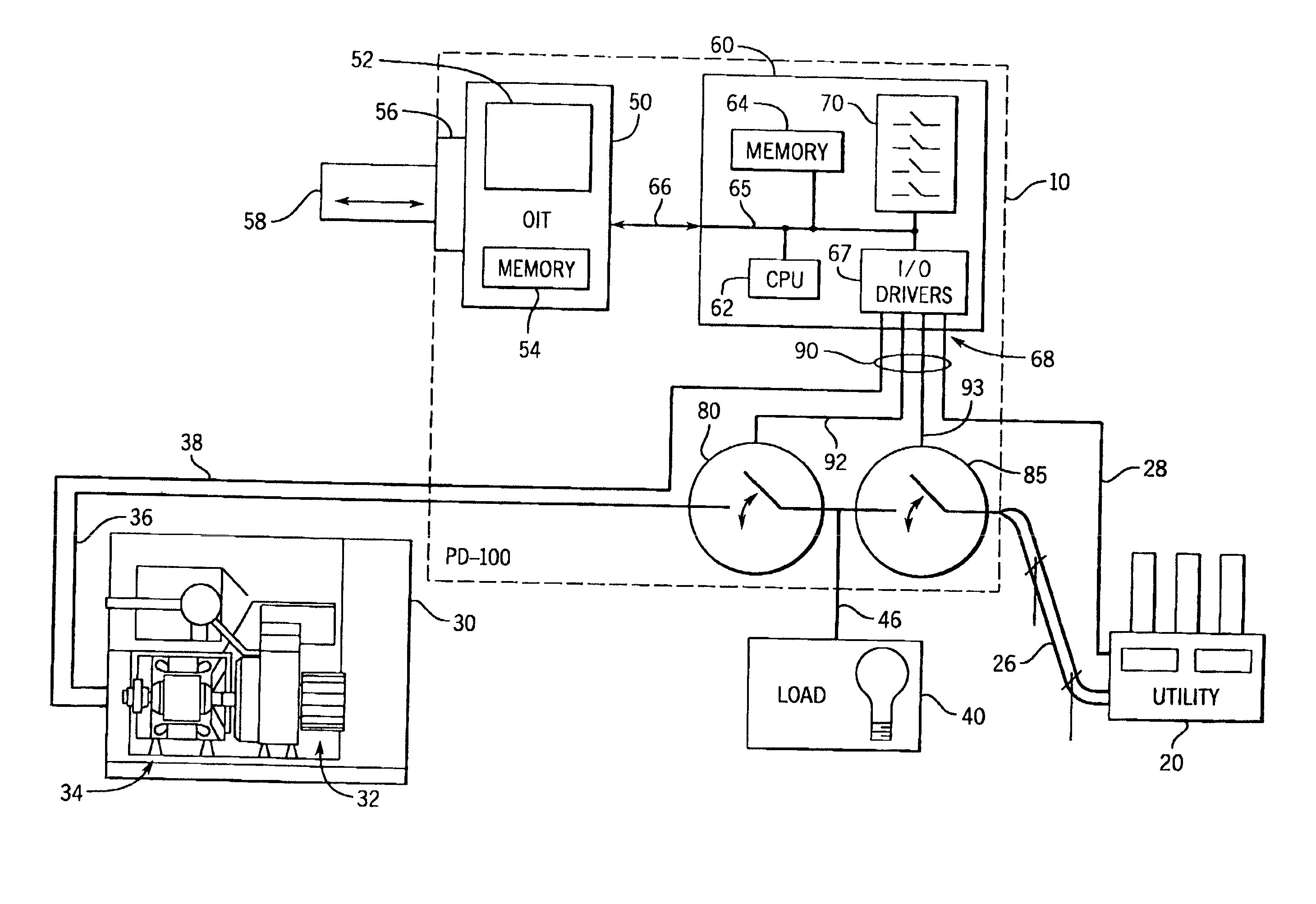
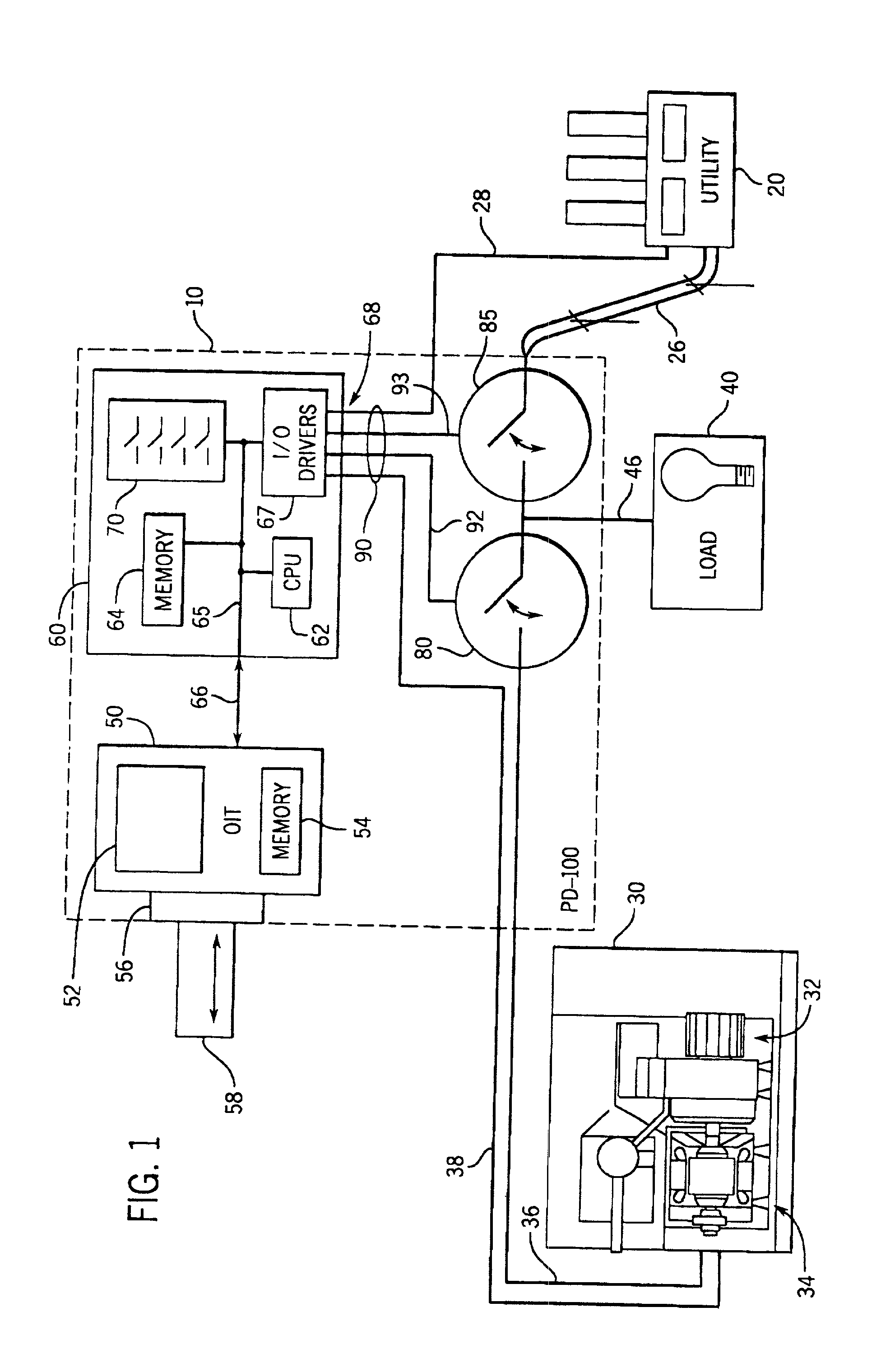
[0018] Referring to FIG. 1, a new configurable switchgear system in accordance with the present invention is typically coupled to a utility 20, a generator set (or "genset")30, and a load 40. The switchgear system 10 operates to determine whether power from the utility 20 is provided to the load 40, whether power from the genset 30 is provided to the load, and / or whether power from the genset 30 is provided to the utility 20 or more generally to the power grid to which the utility is providing power. The switchgear system 10 is coupled to the utility 20 by a power cable or line 26, to the genset 30 by a genset power cable 36, and to the load 40 by a load power cable 46. The genset 30 is shown to be a conventional genset having an internal combustion engine 32 such as the Series 60, Series 2000 or Series 4000 engines manufactured by the Detroit Diesel Co. of Detroit, Mich., as well as an alternator 34, which can be a 3-phase synchronous machine such as the model 5M4027 alternator man...


PUM


Abstract

A switchgear system, as well as a method of controlling a switching status of two switches in a switchgear system, are disclosed. The switchgear system includes a first switch capable of electrically coupling a first power source and a load, and a second switch capable of electrically coupling a second power source and the load. The switchgear system further includes a control unit coupled to both the first and second switches. The control unit includes a memory that stores software, and the control unit is capable of operating in at least two modes and controlling opening and closing of the first and second switches in accordance with those modes based upon the software. The switchgear system additionally includes an operator interface coupled to the control unit. The operator interface is capable of receiving additional information that enables the operation of the control unit in at least one of the at least two modes.

Description

FIELD OF THE INVENTION[0001] The present invention relates to power control systems and, in particular, relates to switchgear systems employed to control the coupling of one or more power sources to a load and to one another.BACKGROUND OF THE INVENTION[0002] Switchgear systems are widely used by customers of utilities to determine whether and when power is provided to the customers' loads from the utilities or power grid, or from other power source(s) that are under the control of the customers. Depending upon the situation, customers may desire that all of their power is provided from the utilities, that all of their power is provided from their own power sources(s), or that power is jointly provided from both types of power sources. When power is jointly provided from both types of sources, the switchgear systems also are capable of determining the relative amounts of power provided from each of the two types of power sources. Further, switchgear systems allow customers to supply ...

Claims


Application Information

Patent Timeline
IPC IPC(8): G05B19/05G05D3/12G05D5/00G05D9/00G05D11/00G05D17/00H02J1/00H02J1/10H02J3/00H02J3/38H02J9/00
CPCG05B19/05G05B2219/15001G05B2219/23075Y10T307/724Y10T307/696Y10T307/305Y10T307/344Y10T307/615
Inventor KRAKOVICH, ALEXANDERRUH, KEITH S.
Owner KOHLER CO
Why Eureka
Try Eureka