Space dividing partition system

a technology of space and partitions, applied in the direction of parkings, walls, building roofs, etc., can solve the problems of time-consuming disconnecting and reconnecting of structural connections of adjacent panels, and the cost of such wall panels necessarily includes the cost of electrical and communication components

Inactive Publication Date: 2002-09-19
KRUEGER INT
View PDF1 Cites 8 Cited by
  • Summary
  • Abstract
  • Description
  • Claims
  • Application Information

AI Technical Summary

Benefits of technology

0006] In accordance with yet another aspect of the invention, a column for a space dividing system includes a structural columnar assembly defining an upper end and a lower end for engagement with the floor. A power receptacle arrangement is interconnected with the structural columnar assembly, and includes one or more outwardly facing receptacles. The structural columnar assembly defines a passageway between its upper end and the power receptacle arrangement, for enabling wiring to pass from the ceiling through the passageway and to the power receptacle arrangement. An adjustable height connection arrangement is adapted for interconnection between the upper end of the structural columnar assembly and the ceiling. In this manner, the structural columnar assembly can be engaged with ceilings of different heights, thus enabling the column to be used in different areas of a building.

Problems solved by technology

While this type of wall construction functions well and has met with success, it involves certain drawbacks.
Further, the cost of such wall panels necessarily includes costs for the electrical and communication components.
In addition, the structural connections of adjacent panels can be time consuming to disconnect and reconnect each time the wall configuration is altered.

Method used


Image

  • Space dividing partition system
  • Space dividing partition system
  • Space dividing partition system

Examples


Embodiment Construction

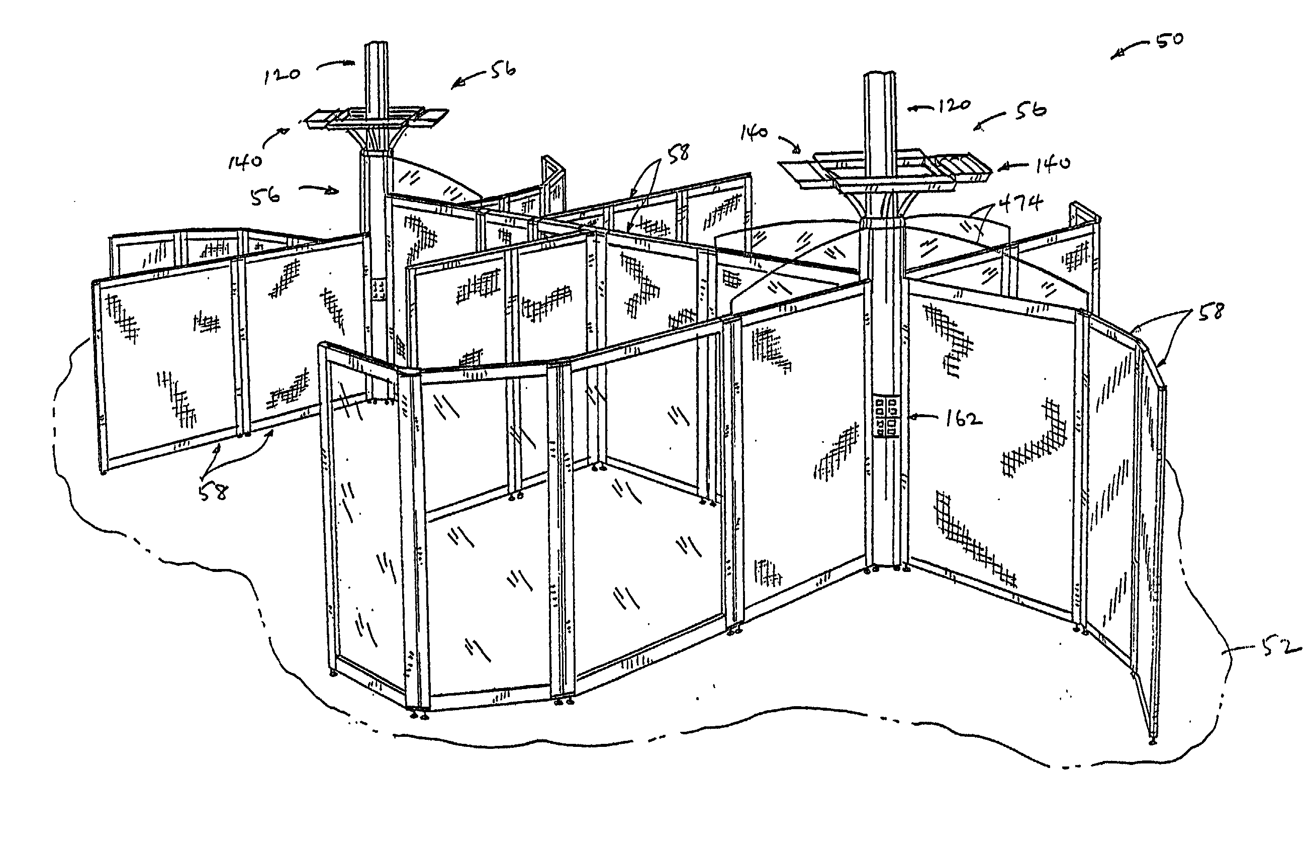
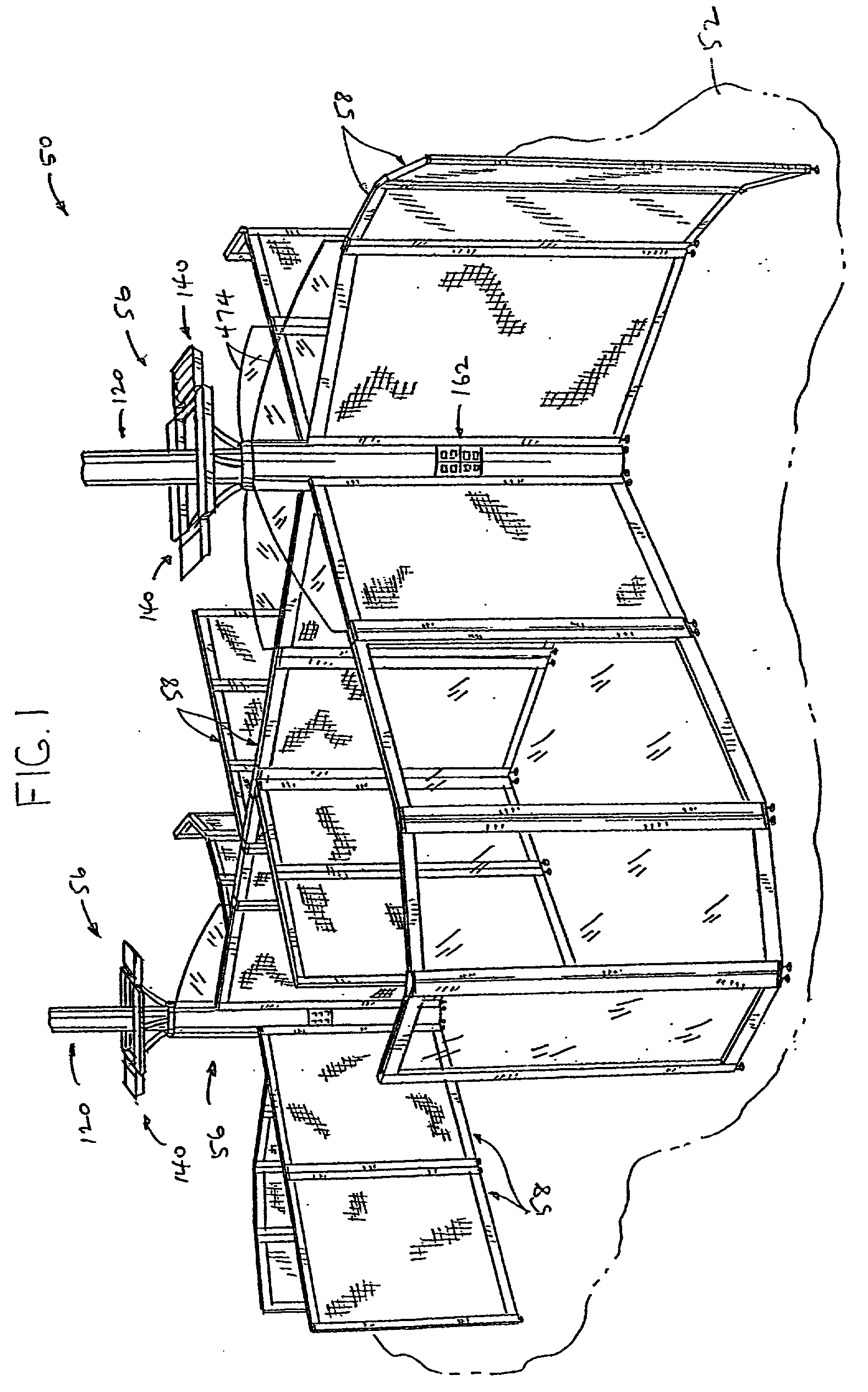
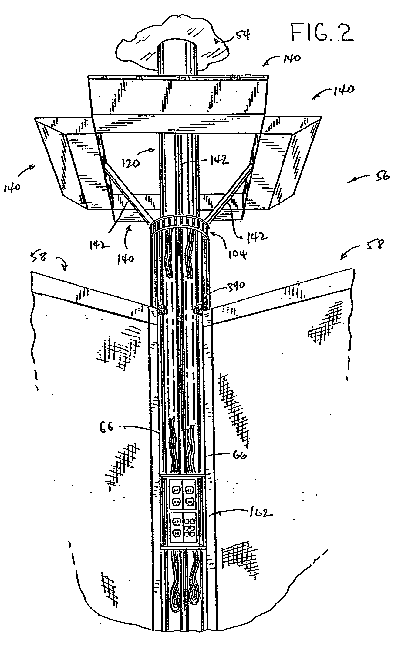
[0068] FIG. 1 illustrates a space dividing or partitioning system 50 constructed in accordance with the present invention. Space dividing system 50 is adapted for use in a building having a floor 52 and a ceiling 54 (FIG. 2), and is operable to divide a larger space into smaller areas. In particular, space dividing system 50 is adapted for use in a workplace environment to divide the space into individual work areas, meeting areas, reception areas or the like. Generally, space dividing system 50 includes a series of columns shown generally at 56, and a series of partition panels shown generally at 58.

[0069] FIGS. 2-16 illustrate the construction of column 56. Referring to FIG. 3, column 56 includes a structural columnar frame assembly 60 including an upper end plate 62 and a lower end plate 64. A series of vertical rods 66 extend between and interconnect upper end plate 62 and lower end plate 64. Each rod 66 defines an upper end received within an opening formed in upper end plate 6...


PUM


Abstract

A space dividing system includes a column and a series of partition panels adapted for interconnection with the column. The column includes an internal passage, and is adapted to receive wiring from a building for supplying power to a receptacle arrangement interconnected with the column. Adjacent panels are connected to the column at spaced locations, and the receptacle arrangement is exposed between the adjacent panels. The column includes a structural skeleton to which the receptacle arrangement is mounted, and a series of covers are releasably engaged with the structural skeleton for finishing the aesthetic appearance of the column. An adjustable height mounting arrangement is interconnected with the upper end of the column for connection to a ceiling to stabilize the upper end of the column. Each panel is in the form of a frame defining an opening within which a core is received. Cover members are releasably engageable with the frame members, and overlie the core so as to releasably maintain the core in position within the opening. End caps are mounted to upper and lower ends of the side frame members, and are utilized to mount various connectors to the panels for interconnecting the panels together and for providing stacking of panels on top of each other.

Description

BACKGROUND AND SUMMARY OF THE INVENTION[0001] This invention relates to a space dividing or partitioning system such as for use in an office environment, and more particularly to such a system incorporating power and communication capabilities.[0002] A wide variety of office space partitioning or dividing systems are known. Many such systems include wall panels which are rigidly interconnected with each other to form a sectioned wall assembly. In such a system, it is common to provide a power distribution system toward the lower end of each wall panel, incorporating power receptacles at spaced locations. It is also known to provide power and / or communication distribution in each panel substantially at desk height. While this type of wall construction functions well and has met with success, it involves certain drawbacks. For example, it is necessary to connect the power and communication components of one wall panel with the power and communication components of an adjacent wall pan...

Claims


Application Information

Patent Timeline
Patent Type & Authority Applications(United States)
IPC IPC(8): E04B2/74
CPCE04B2/7424E04B2/7425E04B2/7429E04B2/7431E04B2002/7483E04B2002/7488E04B2002/749
Inventor DIFFRIENT, NIELSBOUCHE, TIMOTHY J.KOPISH, ANDREW J.
Owner KRUEGER INT
Why Eureka
Try Eureka