Filter and method for manufacturing the filter

a technology for filtering and manufacturing methods, applied in the field of filters, can solve problems such as troublesome removal of filter from the forming mold 52, and achieve the effects of improving the strength of the filter, reducing the risk of deformation, and simplifying the manufacture of the filter

Inactive Publication Date: 2002-09-19
TOYOTA BOSHOKU KK
View PDF7 Cites 4 Cited by
  • Summary
  • Abstract
  • Description
  • Claims
  • Application Information

AI Technical Summary

Benefits of technology

0008] According to this exemplary aspect, because the mold for forming the filter becomes a structural member of the filter, there is no need to remove the filter from the mold. Obviating the need for the operation of removing the filter from the mold in this way thus simplifies the manufacture of the filter.
0009] Also according to this exemplary aspect, the mold can include both a filter portion forming surface for forming a filter portion for filtering a fluid and a frame which surrounds this filter portion forming surface. The frame and the like in this case improves the strength of the filter, making the filter less prone to deformation by negative pressure and the like from the fluid passing therethrough.
0010] Fibers protruding outside of the frame can also be folded inward toward the inside of the frame and then fixed thereto. This obviates the need to cut off protruding fibers and keeps the fibers from being wasted.
0011] Moreover, a flange can be formed on the outer periphery of the frame. Doing this enables fibers to be deposited on the flange, which in turn enables a seal portion to be formed easily when the filter is attached to a housing.
0012] The mold and fibers may also be formed of the same material. If formed of the same material, the mold and the fibers in a semi-molten state fuse together, such that adhesion between the mold and fibers is improved. The filter portion forming surface of the mold may also be formed with a mesh.

Problems solved by technology

That is, although this method simplifies forming the filter 50, removing the filter from the forming mold 52 is troublesome.

Method used


Image

  • Filter and method for manufacturing the filter
  • Filter and method for manufacturing the filter
  • Filter and method for manufacturing the filter

Examples


Embodiment Construction

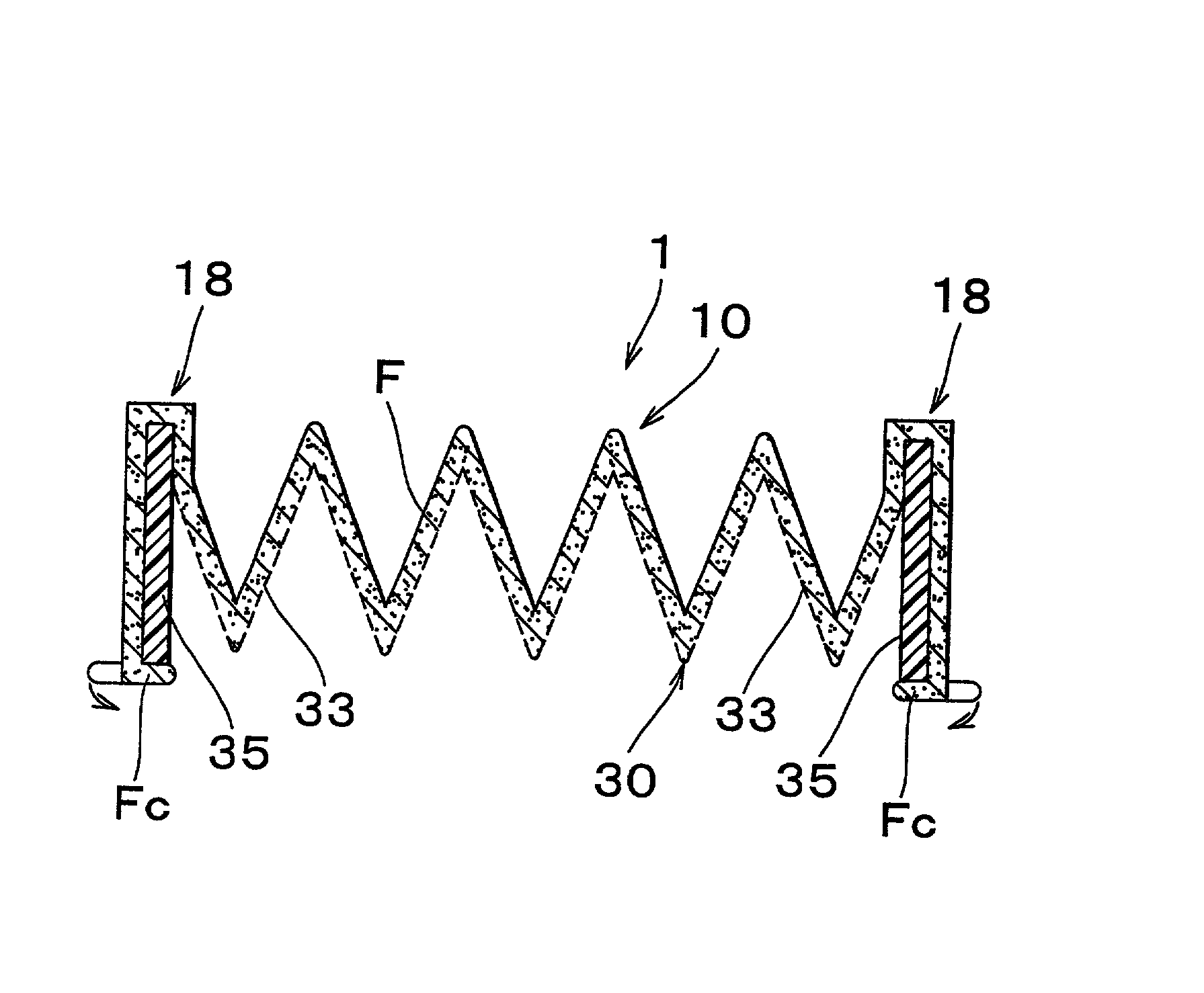
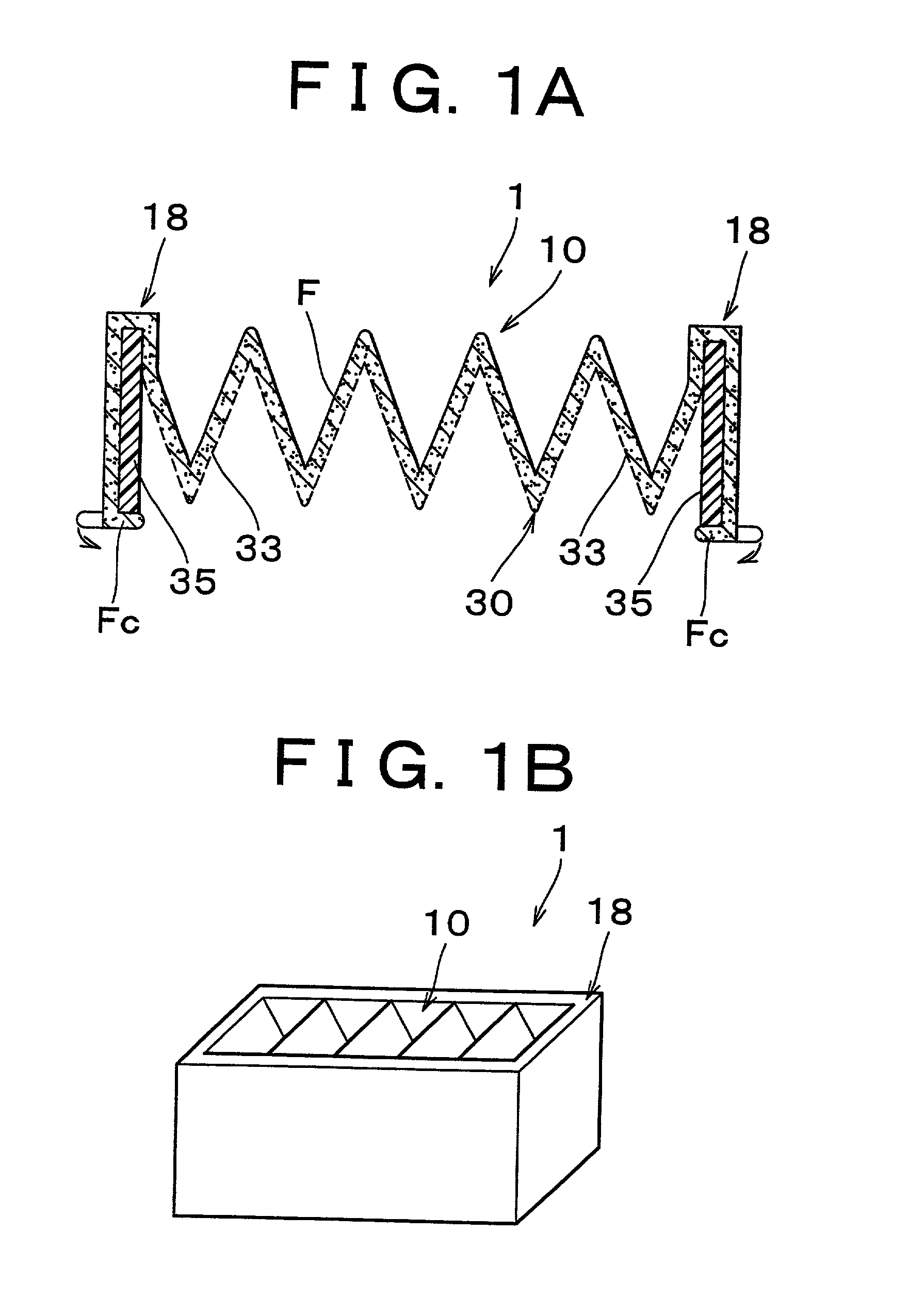
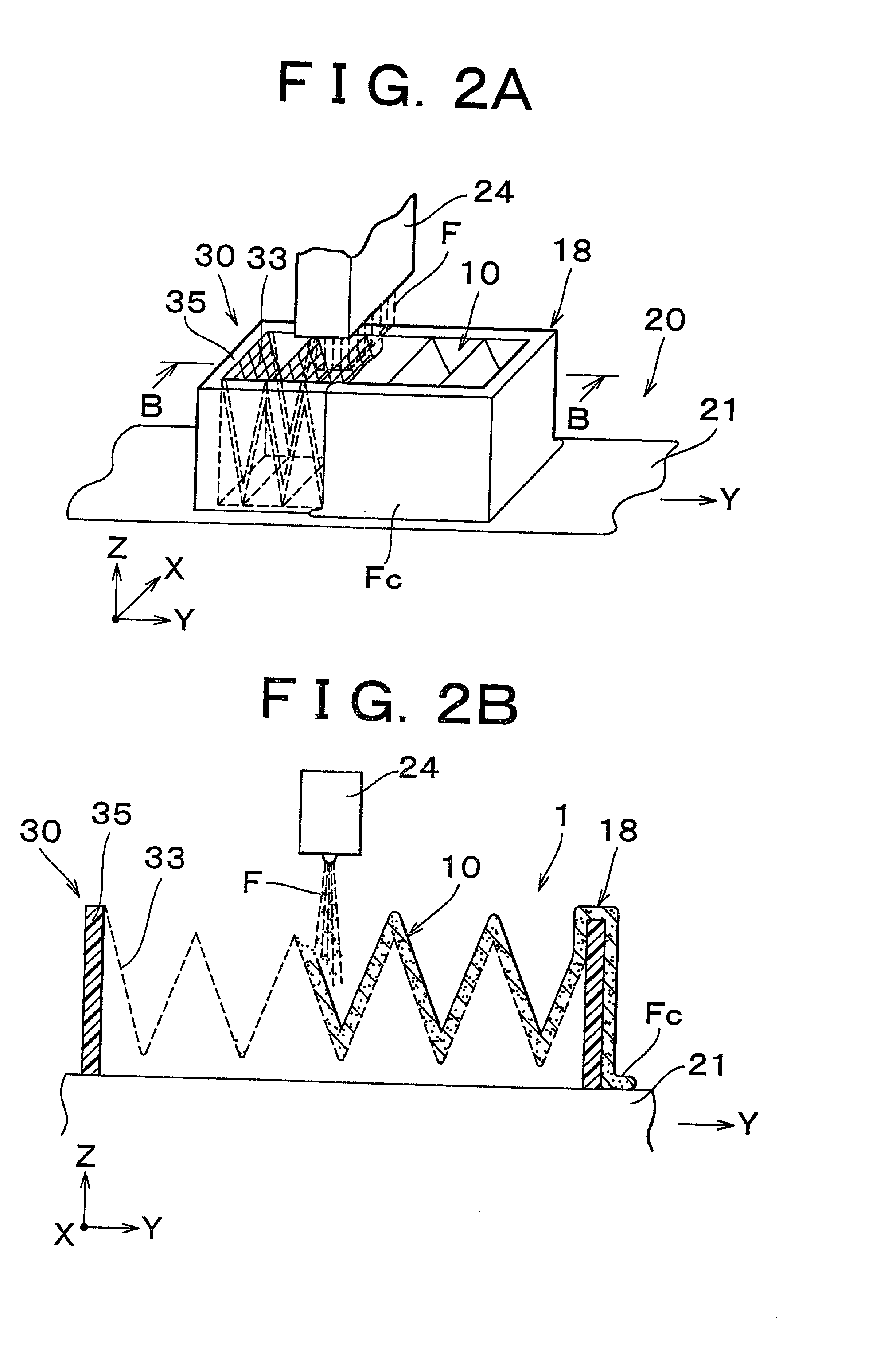
[0019] Hereinafter, a filter and a method for manufacturing a filter according to a first exemplary embodiment of the invention will be explained with reference to FIGS. 1 through 3. FIG. 1A is a longitudinal sectional view of a filter according to a first embodiment of the invention, and FIG. 1B is a perspective view of the filter according to the same embodiment. FIG. 2A is a perspective view illustrating a method for manufacturing a filter, and FIG. 2B is a sectional view taken along line IIB-IIB in FIG. 2A.

[0020] As shown in FIGS. 2A and 2B, a filter 1 according to this exemplary embodiment has a mold portion 30 which is used for forming the filter 1, and which becomes the skeleton of the filter 1 after the filter 1 is formed. A nonwoven fabric F is then deposited at a substantially consistent thickness on this mold portion 30.

[0021] The mold portion 30 includes a mesh plate 33 (denoted by the dotted lines) which is formed in a bellows shape, and a rectangular frame 35 for suppo...


PUM

PropertyMeasurementUnit
thicknessaaaaaaaaaa
strengthaaaaaaaaaa
adhesionaaaaaaaaaa

Abstract

A filter and a method of manufacturing the filter which is formed by spinning a fiber in a semi-molten state onto a mold such that the mold is provided as a filter structural member. The method obviates the need to remove the filter from the mold and thus simplifies the manufacture of the filter.

Description

INCORPORATION BY REFERENCE[0001] The disclosure of Japanese Patent Application No. 2001-71209 filed on Mar. 13, 2001 including the specification, drawings and abstract is incorporated herein by reference in its entirety.BACKGROUND OF THE INVENTION[0002] 1. Field of Invention[0003] The invention relates to a filter formed by spinning fibers that are in a semi-molten state onto a mold, as well as a method for manufacturing the filter.[0004] 2. Description of Related Art[0005] As shown in FIGS. 4A and 4B, in order to improve forming efficiency of a filter, semi-molten fibers F spun from a spinning nozzle 54 are deposited onto a forming surface 52f of a forming mold 52 to form a filter 50 having a shape substantially the same as that of the forming surface 52f (Japanese Patent Application Laid-Open Publication No. 8-38834). After being formed, the filter 50 is then removed from the forming mold 52 and completed with a finishing process.[0006] With this method, however, because the filte...

Claims


Application Information

Patent Timeline
Patent Type & Authority Applications(United States)
IPC IPC(8): B01D39/00B01D29/01B01D39/16B01D46/00B01D46/10B01D46/52D04H1/56D04H3/16
CPCB01D29/012B01D39/1623B01D46/0001B01D46/10B01D46/521B01D29/031D04H3/07D04H3/16Y10S55/31Y10S55/05Y10S264/48D04H3/016
Inventor ODA, KOUICHINISHINO, TOMOHIDE
Owner TOYOTA BOSHOKU KK
Why Eureka
Try Eureka