Torque sensor for vehicle

a technology for torque sensors and automobiles, applied in the direction of instruments, force/torque/work measurement apparatuses, transportation and packaging, etc., can solve problems such as the reliability of products to be deteriorated, and achieve the effect of improving the structure of the detection coil assembly

Inactive Publication Date: 2002-09-19
HL MANDO CORP
View PDF0 Cites 7 Cited by
  • Summary
  • Abstract
  • Description
  • Claims
  • Application Information

AI Technical Summary

Benefits of technology

[0016] Accordingly, the present invention has been made keeping in mind the above problems occurring in the prior art, and an object of the present invention is to provide a torque sensor for automobiles capable of securely maintaining the initial fabricated positions of components to precisely perform detection of torque by improving a structure of its detection coil assembly.

Problems solved by technology

Therefore, the initial positions of the temperature compensating detection assembly 7, whereby the spacer 9 and the magneto-resistance detection coil assembly 8 are varied by being subjected to external vibration or shock, torque acting on the torsion bar 1c cannot be precisely detected, thereby causing reliability of products to be deteriorated.

Method used


Image

  • Torque sensor for vehicle
  • Torque sensor for vehicle
  • Torque sensor for vehicle

Examples


first embodiment

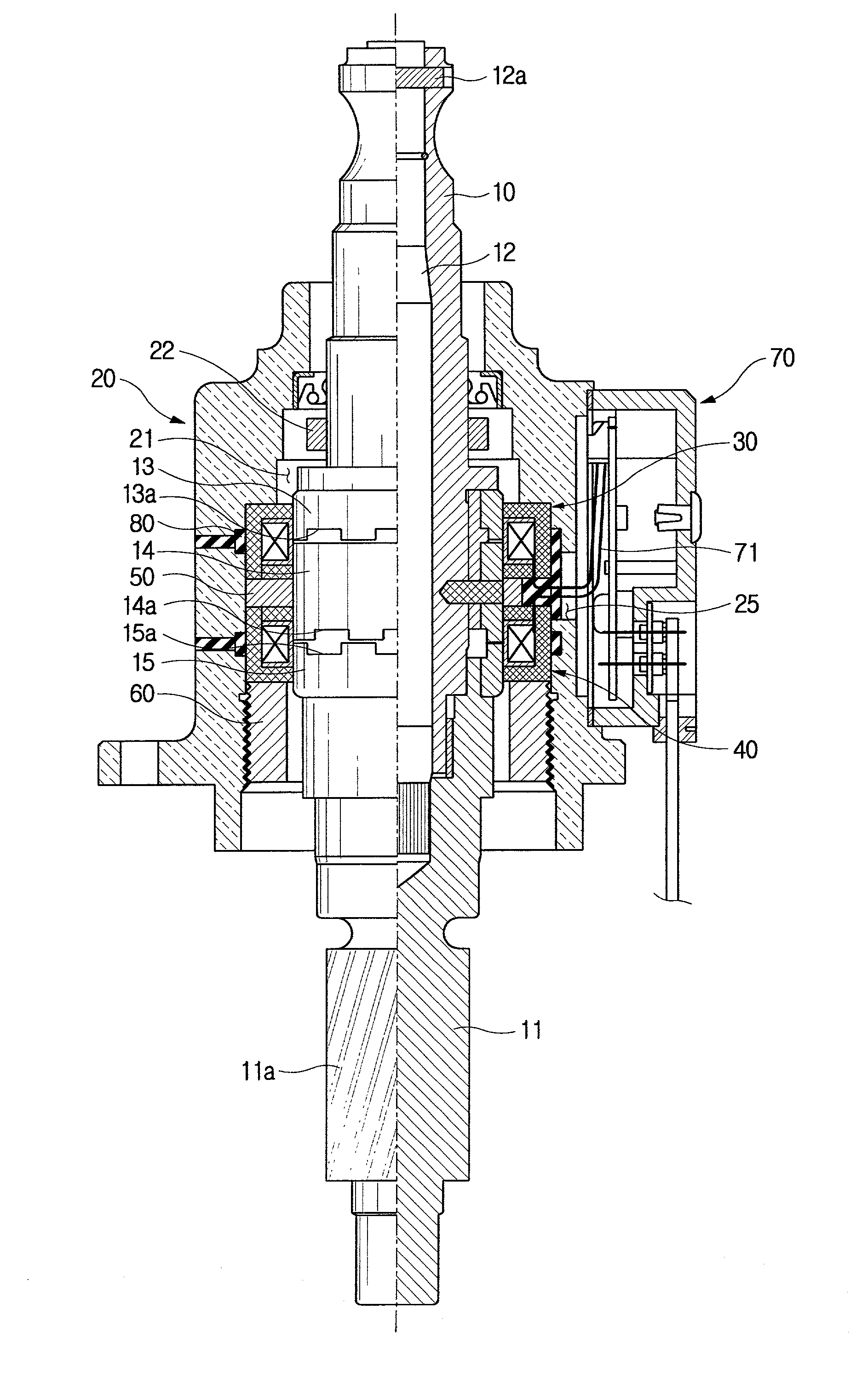
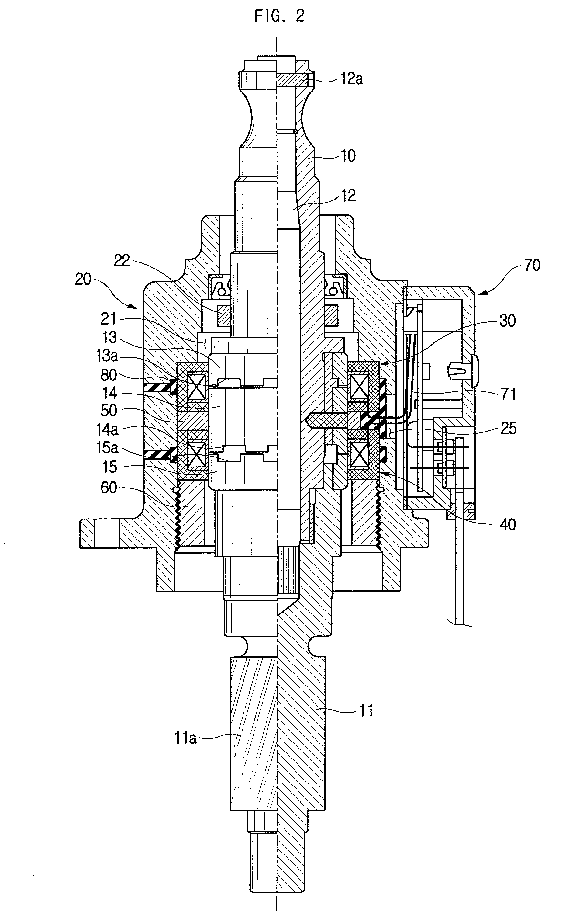
[0052] An operation of the torque sensor according to the present invention will be now described.

[0053] First, when the steering wheel is manipulated by a driver under the condition that an automobile having the torque sensor of the invention incorporated therein travels, the automobile wheels are steered in a desired direction through the input shaft 10, torsion bar 12 and the pinion shaft 11, thereby causing a traveling direction of the automobile to be changed.

[0054] At this point, if excessive steering force is applied to the steering wheel, a rotating angle of the input shaft 10, which is directly rotated through the steering wheel, is larger than that of the pinion shaft 11 connected to the input 10 via the torsion bar 12, thereby causing the torsion bar 12 to be twisted.

[0055] Therefore, areas of the teeth ends 14a and 15a of the second and the third detection rings 14 and 15, which face to each other, are varied. With the variation of the facing areas, inductance value of t...

second embodiment

[0061] Referring to FIG. 7, the torque sensor is constructed such that the temperature compensating detection coil assembly 30, the spacer 50 and the magneto-resistance detection coil assembly 40 are sequentially inserted in the housing 20. For retaining the components in place, the detection coil assemblies 30 and 40 are provided at their outer surfaces with a first and a second grooves 34 and 44, respectively, and the first and the second grooves 34 and 44 are fitted with elastic retaining elements 80, respectively (see FIG. 8).

[0062] The first groove 34 is circumferentially formed along the middle line of the outer surface of the bobbin housing 33 of the temperature compensating detection coil assembly 30, and the second groove 44 is circumferentially formed along the middle line of the outer surface of the bobbin housing 43 of the magneto-resistance detection coil assembly 40. The first and the second grooves 34 and 44 have depth and width sufficient to allow a predetermined am...

third embodiment

[0070] Referring to FIG. 10, the torque sensor also has the temperature compensating detection coil assembly 30, the spacer 50, and the magneto-resistance detection coil assembly 40 received therein. For retaining the components in place, the torque sensor is provided with the first and the second band-shaped grooves 23 and 24 formed at the inner surface of the housing 20, i.e., at the wall of the receiving space 21, and the retaining elements 80 molded in the first and second grooves 23 and 24 by means of a molding apparatus.

[0071] The first groove 23 is circumferentially formed along the middle line of the outer surface of the bobbin housing 33 of the temperature compensating detection coil assembly 30, and the second groove 24 is circumferentially formed along the middle line of the outer surface of the bobbin housing 43 of the magneto-resistance detection coil assembly 40. The first and the second grooves 23 and 24 are communicated to upper and lower portions of the lead-out op...


PUM

PropertyMeasurementUnit
temperatureaaaaaaaaaa
resilientaaaaaaaaaa
angleaaaaaaaaaa

Abstract

A torque sensor for automobiles capable of maintaining initial fabricated positions of components in a housing even though being subjected to thermal expansion or external shock is disclosed. Retaining elements made of resilient material having excellent damping capability are interposed between an inner surface of a housing and each of detection coil assemblies by molding process to enable the components received in the housing to be securely held. Though being subjected to external vibration or shock, the external effect can be absorbed by damping effect of the retaining elements. Though the components in the housing thermally expand due to temperature variation, the retaining elements are elastically deformed to accommodate volume increase by the thermal expansion. Since fabricated positions of the components can be securely maintained without axial and radial displacement, it is possible to precisely detect torque acting on a torsion bar.

Description

BACKGROUND OF THE INVENTION[0001] 1. Field of the Invention[0002] The present invention relates to a torque sensor adapted to be used in a power steering system, and, more particularly to a torque sensor for automobiles having a temperature compensating detection coil assembly, a spacer, and a magneto-resistance detection coil assembly incorporated into a housing.[0003] 2. Description of the Prior Art[0004] In general, a torque sensor for automobiles is usually used in a power steering system for intensifying rotating force of a steering wheel, and functions to sense a twisted condition of a torsion bar during rotation of the steering wheel. FIG. 1 shows an inner structure of such a conventional torque sensor for automobiles.[0005] As illustrated in the drawing, the conventional torque sensor for automobile includes a torsion bar 1c adapted to concentrically connect a lower end of an input shaft 1a and an upper end of a pinion shaft 1b, a plurality of detection rings 4, 5 and 6 coup...

Claims


Application Information

Patent Timeline
Patent Type & Authority Applications(United States)
IPC IPC(8): B62D5/04B62D5/06G01L3/10G01L5/22
CPCB62D6/10G01L3/101G01L5/221G01L3/104
Inventor JONG, DAI-CHUNGNO, HEE-DONGNAM, GUNG-JOOKIM, JI-WOONGKIM, KI-WON
Owner HL MANDO CORP
Why Eureka
Try Eureka