Chemical vapor deposition apparatuses and deposition methods

a technology of chemical vapor and deposition apparatus, which is applied in the direction of chemically reactive gas growth, crystal growth process, polycrystalline material growth, etc., can solve the problems of deviation from ideal conditions, undesirable deposition of chamber components, and often not achieved ideal theoretical deposition or intentional modification

Inactive Publication Date: 2002-09-19
MICRON TECH INC
View PDF36 Cites 240 Cited by
  • Summary
  • Abstract
  • Description
  • Claims
  • Application Information

AI Technical Summary

Problems solved by technology

In practice, the ideal theoretical deposition is often not achieved or may be intentionally altered.
One potential cause for a deviation from ideal conditions is the simultaneous presence of the first precursor and the second precursor somewhere in a deposition apparatus other than on the substrate.
Similarly, failure to completely purge one of the precursors from a deposition chamber may cause unwanted deposition on chamber components when the other precursor is introduced.
Unwanted mixing of precursors can be a leading cause of particulate formation and product contamination in ALD.
Unfortunately, careful purging increases process time and accompanying process costs.

Method used


Image

  • Chemical vapor deposition apparatuses and deposition methods
  • Chemical vapor deposition apparatuses and deposition methods
  • Chemical vapor deposition apparatuses and deposition methods

Examples


Embodiment Construction

[0014] This disclosure of the invention is submitted in furtherance of the constitutional purposes of the U.S. Patent Laws "to promote the progress of science and useful arts" (Article 1, Section 8).

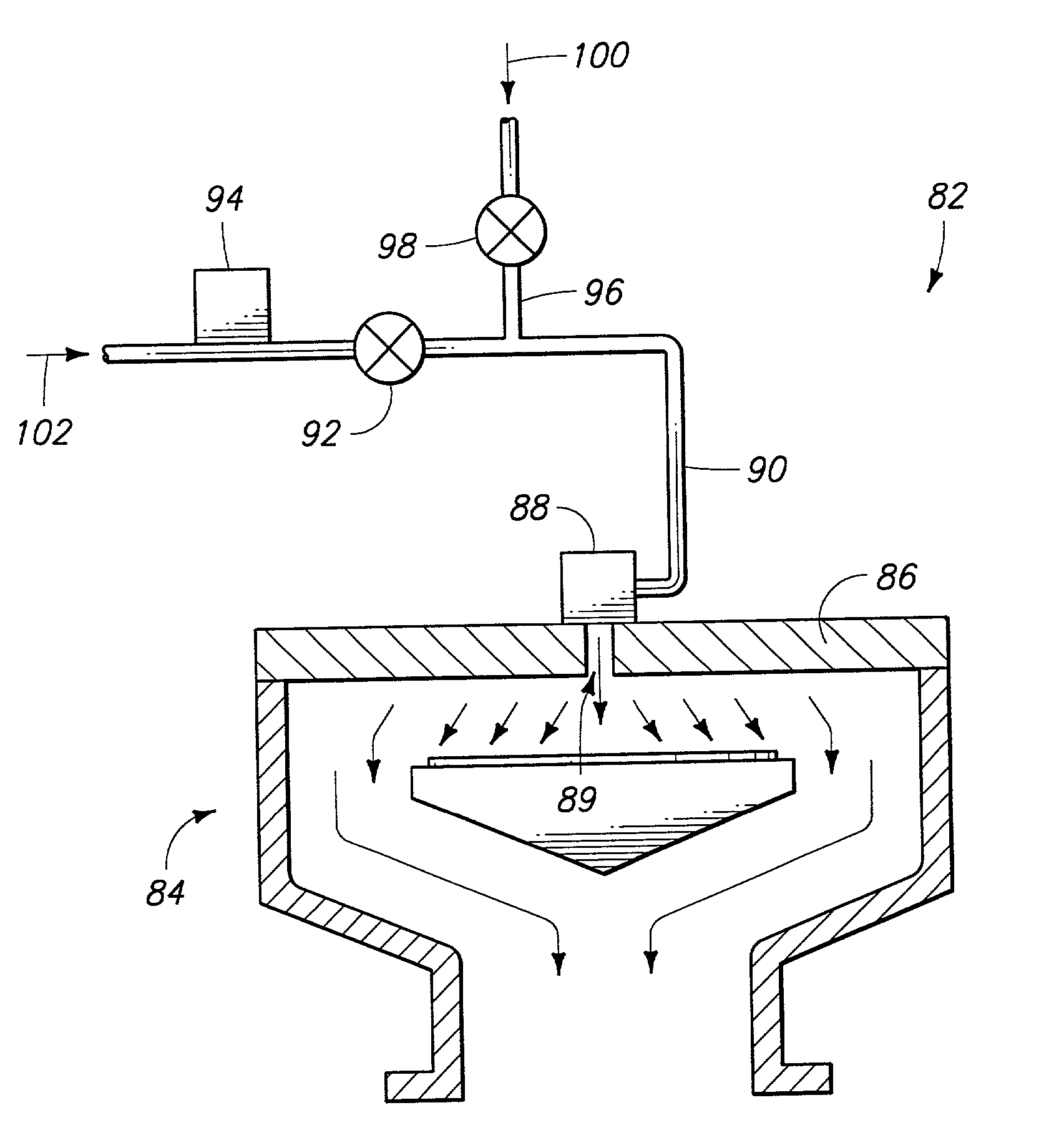
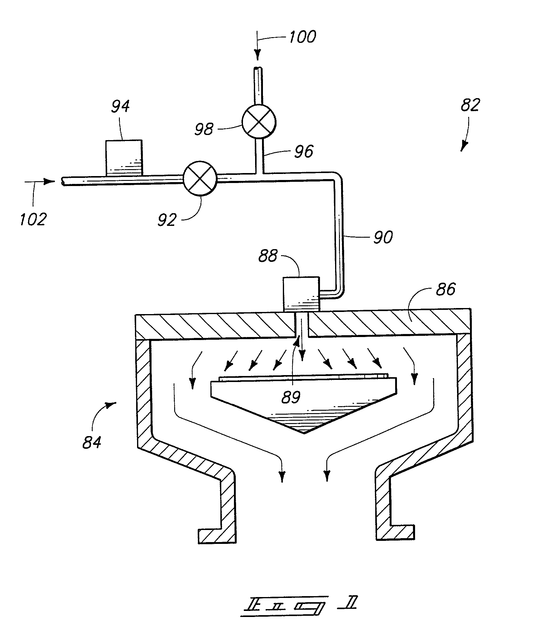
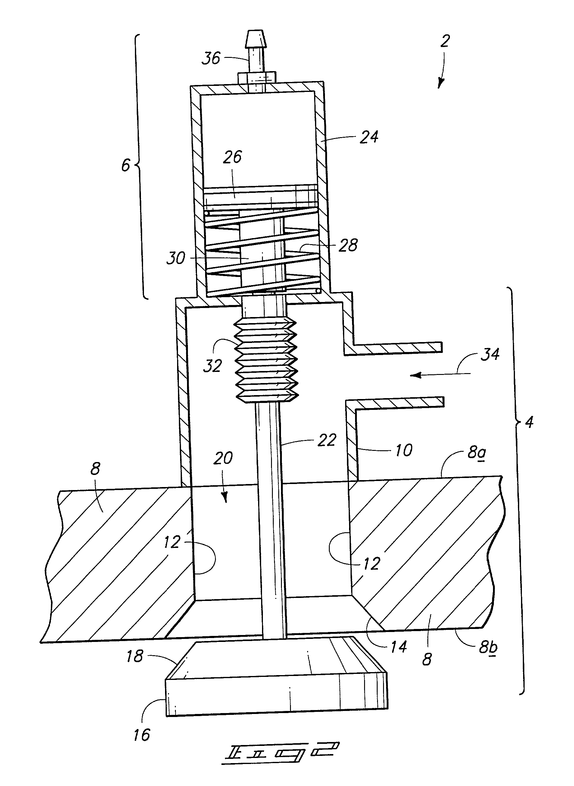
[0015] It is a disadvantage of current atomic layer deposition (ALD) chambers that control valves or shut off valves for gas or liquid precursors, reactants, carriers, purges, and other process chemicals are distant from a deposition chamber. After exiting a final process valve, materials may travel a substantial distance, for example about 25 cm (10 inches), before entering a deposition chamber. The supply line between the closest valve to a deposition chamber and the deposition chamber is typically purged of a first precursor prior to injecting a second precursor in ALD. Accordingly, decreasing the distance between a valve and the chamber can decrease purge time. One possible advantage of some aspects of the invention described herein is that the distance between the closest valve to a...


PUM

PropertyMeasurementUnit
distanceaaaaaaaaaa
chemicalaaaaaaaaaa
flow rateaaaaaaaaaa

Abstract

A chemical vapor deposition (CVD) apparatus includes a deposition chamber defined partly by a chamber wall. The chamber wall has an innermost surface inside the chamber and an outermost surface outside the chamber. The apparatus further includes a valve body having a seat between the innermost and outermost surfaces of the chamber wall. The chamber wall can be a lid and the valve can include a portion of the lid as at least a part of the seat. The valve body can include at least a part of a valve housing between the innermost and outermost surfaces of the chamber wall. Such a valve body can even include a portion of the chamber wall as at least part of the valve housing. The deposition apparatus can further include at least a part of a process chemical inlet to the valve body between the innermost and outermost surfaces of the chamber wall. In one example, the chamber wall can form at least a part of the chemical inlet. A deposition method includes temporarily isolating a process chemical supply line from a deposition chamber at a chamber wall of the deposition chamber. While isolated at the chamber wall, the supply line can be filled to a first pressure with chemical through a supply valve upstream from the chamber wall. The chemical can be released from the supply line into the deposition chamber at the chamber wall. The supply line can be again temporarily isolated from the deposition chamber at the chamber wall.

Description

TECHNICAL FIELD[0001] The present invention pertains to chemical vapor deposition apparatuses, such as atomic layer deposition apparatuses, and deposition methods.BACKGROUND OF THE INVENTION[0002] Chemical vapor deposition (CVD) methods, such as atomic layer deposition (ALD) methods, are often used in semiconductor processing and other industrial applications to form thin layers of materials. One consideration in selecting a deposition method is the process time to form a desired layer. Along with an increasing need to reduce processing costs, a related desire exists to reduce process time. Speaking generally of ALD, a substrate is exposed to a first precursor material that is chemisorbed onto the substrate. The first precursor material is purged from the deposition chamber and a second precursor material chemisorbed onto the first precursor material on the substrate. Theoretically, the chemisorption of each precursor material is self limiting and the deposited material is formed on...

Claims


Application Information

Patent Timeline
Patent Type & Authority Applications(United States)
IPC IPC(8): C23C16/44C23C16/455C30B25/08
CPCC23C16/45544C30B25/08
Inventor CARPENTER, CRAIG M.DANDO, ROSS S.CAMPBELL, PHILIP H.MARDIAN, ALLEN P.FUSS, JEFF N.MERCIL, RANDY W.
Owner MICRON TECH INC
Why Eureka
Try Eureka