Low-noise type steel crawler belt and vehicle employing said crawler belt

Inactive Publication Date: 2002-09-19
TAKEUCHI SEISAKUSHOKK
View PDF0 Cites 6 Cited by
  • Summary
  • Abstract
  • Description
  • Claims
  • Application Information

AI Technical Summary

Benefits of technology

[0005] An object of the present invention is to provide a low-noise type steel crawler belt having a structure capable of reducing the travel noise while maintaining the advantages of the strength, durability and easy repairs that steel crawler belts have.
[0007] With a crawler belt structured as described above, the crawler wheel contacts the steel inner shoe members and engages with the crawler belt, and it is thereby possible to secure the strength of the portion contacting the crawler wheel and to improve the strength and durability of the crawler belt. Further, as the steel outer shoe members mounted on the outer periphery contact the road surface, it is also possible to improve the strength and durability of such portion. And when such steel outer shoe members become worn or damaged, it is possible to independently replace each of such outer shoe members. Repair may thereby be conduced easily and at low cost. In addition, as a rubber belt member is retained between the inner and outer shoe members and such inner and outer shoe members are mounted side by side in the longitudinal direction, the noise caused by the impact of the inner shoe members and the crawler wheel is absorbed by the rubber belt member, and the travel noise is reduced thereby. Moreover, as a wire member embedded in the belt member is formed in a ring shape so as to circumvent the crawler belt, the tensility of the wire member inhibits the crawler belt from being pulled inside upon being wound into the crawler wheel. Thus, the force of the impact of the inner shoe members and the crawler wheel is weakened, and the travel noise is reduced thereby.
[0008] It is preferable that the inner shoe members are embedded in the belt member and integrated thereto in a state where the portion contacting the crawler wheel at the inner periphery and the portion connected to the outer shoe members at the outer periphery are exposed, and the outer shoe members are connected to the inner shoe members by means of bolts at the outer exposed portion of the inner shoe members. Thereby, it is possible to connect the inner shoe members in an endless ring shape while being arranged side by side on the inner face with the belt member, and a crawler belt may be prepared by respectively connecting the outer shoe members with bolts to the portion exposed to the outer face of the inner shoe members. Thus, it is possible to easily attach and detach the respective outer shoes independently. And when such outer shoe members contacting the road surface during the traveling motion become worn or damaged, it is possible to independently and easily replace each of such outer shoe members.

Problems solved by technology

Nevertheless, such rubber crawler belts have problems in that the strength and durability are inferior in comparison to crawler belts structured by linking steel shoes, and in that it is necessary to replace the entire crawler belt even in cases where only a part of the crawler belt is damaged (particularly the travel face which contacts the ground).
Here, the steel crawler belt is superior in strength and durability and there is an advantage in that the respective shoes may be replaced or repaired separately, but there is a problem in that the travel noise from the crawler belt during the traveling motion is loud.

Method used


Image

  • Low-noise type steel crawler belt and vehicle employing said crawler belt
  • Low-noise type steel crawler belt and vehicle employing said crawler belt
  • Low-noise type steel crawler belt and vehicle employing said crawler belt

Examples


Embodiment Construction

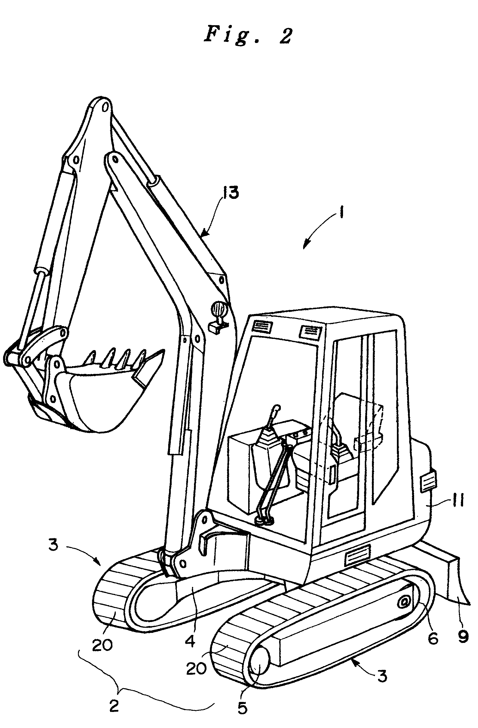
[0019] The preferred embodiments of the present invention are now described with reference to the relevant drawings. FIG. 2 shows a crawler-type power shovel vehicle 1 employing the low-noise type steel crawler belt of this invention. This power shovel vehicle 1 comprises a travel dolly 4 having a travel device 2 structured with a pair of left and right crawler belts 20, a blade 9 provided to move freely upward and downward in an oscillatable manner at the rear of this travel dolly 4, a swivel slide 11 provided swivelably on the travel dolly 4, a power shovel mechanism 13 pivotally supported at the front portion of the swivel slide 11, and an operator cabin 15 provided on the swivel slide 11.

[0020] The travel device 2 comprises a travel dolly 4 having an approximate H shape, and a travel mechanism 3 provided on the left and right sides of this travel dolly 4. The travel mechanism 3 comprises a drive sprocket wheel 5 (crawler wheel) provided in the front part of the left and right si...


PUM


Abstract

The crawler belt 20 is structured of a plurality of inner shoes 21; a plurality of outer shoes 30 arranged to oppose each of the inner shoes; an endless ring-shaped rubber belt member 26 retained between the inner shoes and outer shoes respectively opposing each other; and an endless ring-shaped steel wire 27 embedded in the belt member extending in the longitudinal direction. The inner shoes 21 are arranged side by side along the inner periphery of the belt member, the outer shoes are arranged side by side along the outer periphery of the belt member, and concave portions are arranged in the longitudinal direction between the inner shoes and formed openly toward the inner periphery for receiving the sprocket teeth. Thereby, it is possible to reduce the travel noise while maintaining the advantages of the strength, durability and repairability of steel crawler belts.

Description

FIELD OF THE INVENTION[0001] The present invention is directed to an endless ring-shaped crawler belt which is placed around a pair of crawler wheels and rotatably driven between such crawler wheels when one of the crawler wheels is rotatably driven.[0002] Further, there are those in which the pair of crawler wheels is respectively structured of a sprocket wheel comprising sprocket teeth for driving one of the crawler wheels, and those in which one is a sprocket wheel and the other is a sprocketless cylindrical idler wheel for driving the sprocket wheel. Such sprocket wheels and idler wheels are hereinafter collectively referred to as crawler wheels.BACKGROUND OF THE INVENTION[0003] This type of crawler belt is generally used on vehicles known as crawler vehicles. The ground pressure of crawler vehicles is low, and they are therefore employed for various uses; for example, construction machinery, as such crawler vehicles are capable of travelling at locations with unfavorable road c...

Claims


Application Information

Patent Timeline
IPC IPC(8): B62D55/253
CPCB62D55/253
Inventor SHIMADA, YOSHIHIDEKOBAYASHI, KAZUYUKI
Owner TAKEUCHI SEISAKUSHOKK
Why Eureka
Try Eureka