Form-adaptable electrode structure in layer construction

Inactive Publication Date: 2002-09-19
AIRBUS DEFENCE & SPACE
View PDF8 Cites 3 Cited by
  • Summary
  • Abstract
  • Description
  • Claims
  • Application Information

AI Technical Summary

Benefits of technology

[0011] Such a layer structure may be distinguished by a simple construction which may be produced using customary vapor deposition processes. In addition, by applying a crack-stopper layer between the base material and the first conductor layer, the transfer of cracks to the layer structure is reduced or avoided. The base material may include a piezoceramic plate, a piezoelectric element, a fibrous composite structure having piezoelectric structures, etc. Generally, the final insulating layer may be used to protect the layer structure.
[0013] According to a further example embodiment of the present invention for generating a desired field distribution in a piezoelectric element, positive voltage is applied to the first electrode strips of the first conductor layer and negative voltage is applied to the second electrode strips of the second conductor layer, or vice versa. In the same manner, the first electrode strips of the second conductor layer may receive positive voltage and the second electrode strips of the first conductor layer may receive negative voltage, or vice versa. That is, the electrode strips may be interconnected as desired depending on the application case. This also implies that the sequence of the interconnection may be arbitrarily selected. That is, first and second electrode strips do not necessarily have to receive voltages of different polarity. Thus, the electrode structure of the present invention is distinguished by an extremely flexible applicability.
[0014] Furthermore, the electrode structure of the present invention may have the distinction that the angle between the electrode strips of the first conductor layer and the electrode strips of the second conductor layer is adjustable within a wide range from 0.degree. to 180.degree.. The angle may be, for example, 90.degree.. However, it may be important that the exact value of the angle is not critical, so that high accuracy is not necessary during manufacturing. This simplifies the manufacturing process and keeps production costs low.

Problems solved by technology

This is particularly necessary when interconnecting or wiring bendable, movable or deformable components, since due to the deformation, the metallic electrode strips generally applied on the component by vapor deposition may get cracks or fractures.

Method used


Image

  • Form-adaptable electrode structure in layer construction
  • Form-adaptable electrode structure in layer construction

Examples


Embodiment Construction

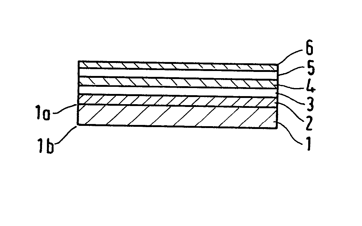
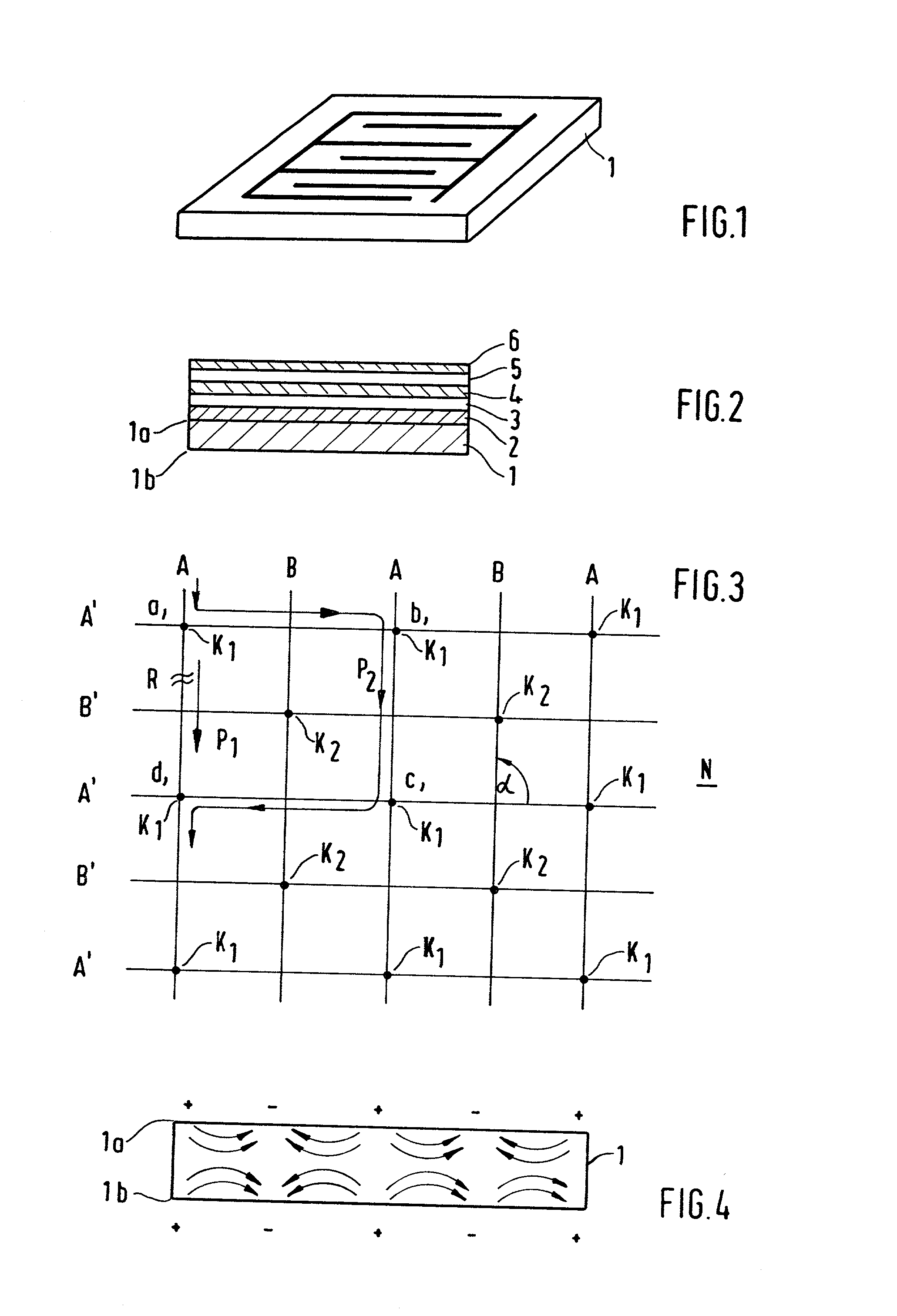
[0020] FIG. 2, in schematic representation, illustrates a cross-section through an electrode structure of the present invention in layer construction which is formed on a base material 1. For the sake of simplicity, in FIG. 2, the layer construction is illustrated merely on one surface 1a of base material 1. However, base material 1 may be provided with such a layer structure on both surface sides 1a, 1b. Base material 1 may include a piezoceramic structure or a fibrous composite structure having piezoelectric elements. Moreover, base material 1 may be any electronic component such as a semiconductor transistor, an interdigital transducer, etc. Base material 1 may exhibit a certain flexibility, permitting adaptation to curved structures by bending and deformation.

[0021] As illustrated in FIG. 2, a first layer 2 is arranged on surface 1a of base material 1. This first layer is used as a crack stopper and is typically 2 .mu.m thick. This crack-stopper layer 2 is made, for example, of ...


PUM


Abstract

A form-adaptable electrode structure in layer construction includes at least two conductor layers, between which an insulating layer is disposed, the conductor layers having first and second electrode strips arranged in each case in parallel, and the electrode strips of the first conductor layer being arranged at an angle with respect to the electrode strips of the second conductor layer, so that a net-like structure is formed, and the first electrode strips of the first conductor layer being conductively interconnected with the first electrode strips of the second conductor layer, and the second electrode strips of the first conductor layer being conductively interconnected with the second electrode strips of the second conductor layer via the insulating layer at intersections of the net-like structure.

Description

FIELD OF THE INVENTION[0001] The present invention relates to a form-adaptable electrode structure in layer construction, e.g., for the contacting of flexible and bendable structures. For example, such structures may be piezoelectric elements in sensor and / or actuator systems.BACKGROUND INFORMATION[0002] The use of interdigital electrode structures for contacting electronic components, such as bipolar transistors, surface transducers, piezoelectric sensor- / actuator systems and the like, is conventional. Such a conventional interdigital electrode arrangement is illustrated schematically in FIG. 1. The interdigital electrode structure is usually applied at least on one surface of the electronic component. For protection purposes, generally, a final protective layer is applied on the electrode arrangement, which in turn was applied by vapor deposition or the methods (e.g., laminating, etching) conventional from printed circuit board technology. However, this protective layer cannot be ...

Claims


Application Information

Patent Timeline
IPC IPC(8): H01L41/047
CPCH01L41/047H10N30/87
Inventor HERMLE, FRANKJANKER, PETER
Owner AIRBUS DEFENCE & SPACE
Why Eureka
Try Eureka