Film forming apparatus and film forming method

Inactive Publication Date: 2002-09-19
SEMICON ENERGY LAB CO LTD
View PDF3 Cites 47 Cited by
  • Summary
  • Abstract
  • Description
  • Claims
  • Application Information

AI Technical Summary

Problems solved by technology

The most serious problem of practical use of these light-emitting elements lies in that the element's life is insufficient.
Furthermore, inclusion of impurities of an organic material and an inorganic material in an or

Method used


Image

  • Film forming apparatus and film forming method
  • Film forming apparatus and film forming method
  • Film forming apparatus and film forming method

Examples


embodiments 1

[0086] In the present embodiment, a method will be described in which vapor deposition is conducted onto a substrate provided in a film forming chamber, using a vaporization source obtained by heating an organic compound for forming a high-purity region by a heater among an organic compound provided in a crucible in a purifying chamber, as described in Embodiment Mode 1.

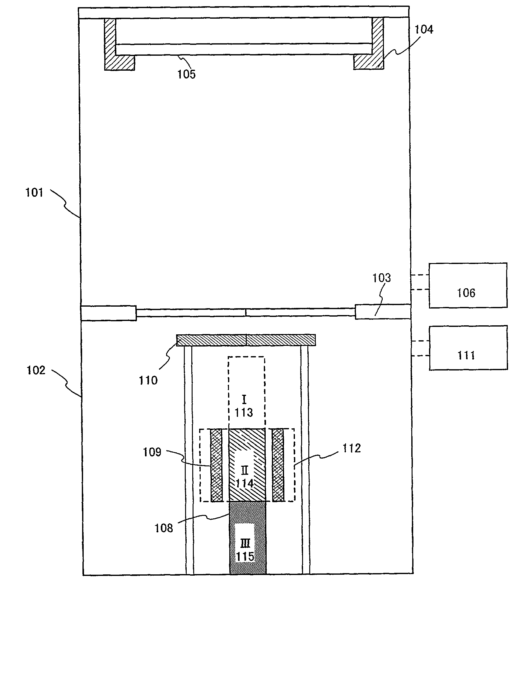
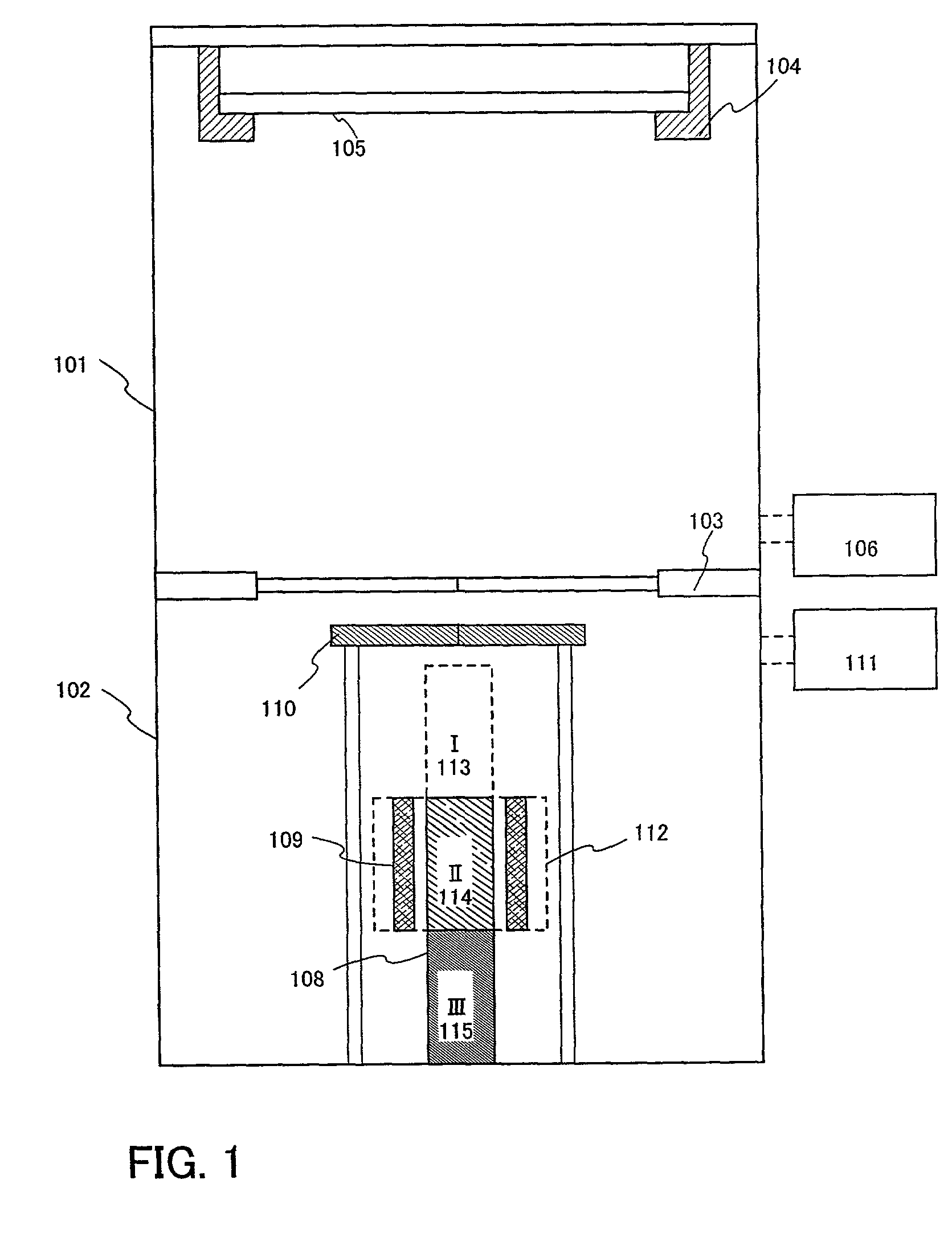
[0087] FIG. 5 shows cross-sectional structures of a film forming chamber and a purifying chamber in a film forming apparatus of the present embodiment. In FIG. 5, a film forming chamber 501 and a purifying chamber 502 are connected to each other via a gate 503. The purifying chamber 502 is disposed under the film forming chamber 501. In the film forming chamber 501, a substrate 505 is disposed by a substrate holder 504. The substrate 505 includes the state where a thin film is formed on the surface thereof.

[0088] A metal mask 506 is provided in the vicinity of the substrate 505, and the metal mask 506 is supported by...

embodiment 2

[0105] In the present embodiment, a method will be described in which a crucible having a high-purity region in an organic compound provided in a crucible in a purifying chamber is carried to a vaporization source in a film forming chamber by a carrier mechanism, and evaporation is conducted onto a substrate provided in the film forming chamber, as described in Embodiment Mode 2. The crucible in the present embodiment has a structure in which a plurality of crucibles are stacked on each other as shown in FIG. 4A. Therefore, even if a high-purity region is formed at any position of the crucible, only a highly purified organic compound can be easily taken out without removing an impurity by vaporization as in Embodiment 1.

[0106] FIG. 6 shows cross-sectional structures of a film forming chamber and a purifying chamber in a film forming apparatus of the present embodiment. In FIG. 6, a film forming chamber 601 and a purifying chamber 602 are connected to each other via a gate 603. In th...

embodiment 3

[0124] In the present embodiment, the case will be described in which a plurality of heaters are provided with respect to one crucible.

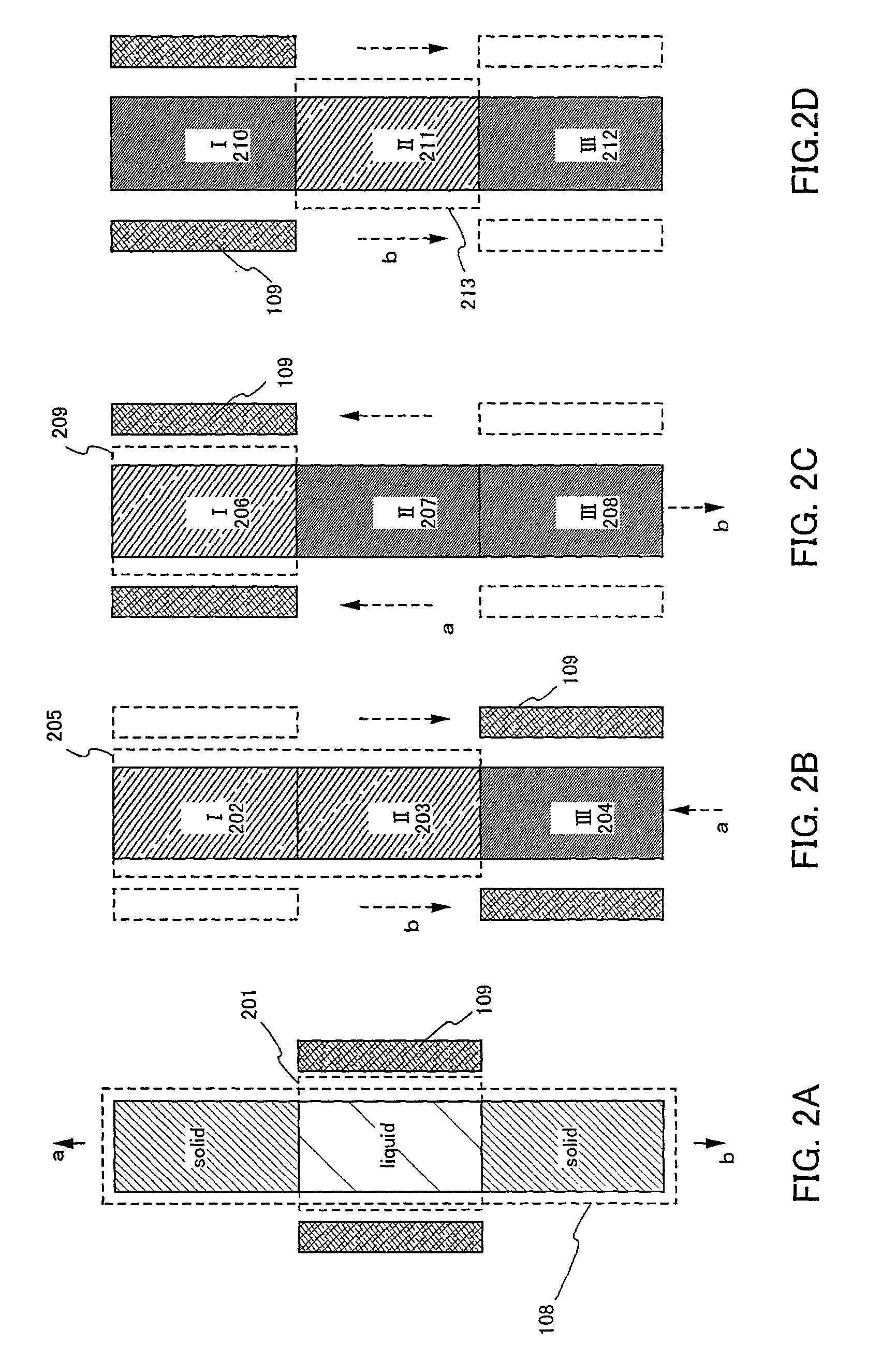
[0125] FIG. 7A shows a crucible and heaters provided in a film forming chamber. A crucible 701 is provided with a solid organic compound.

[0126] A heater I (707), a heater II (708), and a heater III (709) are provided so as to heat a region I (702), a region III (704), and a region V (706) of the crucible 701.

[0127] The crucible 701 is moved at a speed of 1 to 5 cm / h in a direction represented by an arrow "a" while being heated with the heaters. Therefore, a melted zone in a liquid state is formed in the regions heated by the heaters, and a solid state is formed in the regions not heated by the heaters, as shown in FIG. 7B.

[0128] By repeatedly forming a solid state and a liquid state by a plurality of heaters, the purity of an organic compound can be enhanced.

[0129] In the present embodiment, the case has been described in which three heaters are prov...


PUM

PropertyMeasurementUnit
Temperatureaaaaaaaaaa
Speedaaaaaaaaaa
Purityaaaaaaaaaa

Abstract

To provide a film forming apparatus in which an impurity contained in an organic compound is separated to be removed and a film is formed without decreasing the purity of the purified organic compound, whereby a high-purity organic compound is formed. A film forming apparatus of the present invention includes a purifying chamber for purifying an organic compound and a film forming chamber for vapor-depositing the purified organic compound onto a substrate. The organic compound purified by a zone melting method in the purifying chamber can be vapor-deposited onto the substrate provided in the film forming chamber without decreasing the purity thereof, so that a high-purity organic compound layer can be formed.

Description

[0001] 1. Field of the Invention[0002] The present invention relates to a film forming apparatus and a film forming method used for producing a light-emitting element including a film (hereinafter, referred to as an "organic compound layer") containing an organic compound that emits light by the application with an electric field, an anode, and a cathode. In particular, the present invention relates to production of a light-emitting element that is more unlikely to be degraded and has a longer life as compared with the conventional example.[0003] 2. Description of the Related Art[0004] In recent years, a light-emitting apparatus having an organic light-emitting element as a self-luminous element is being actively studied. In particular, a light-emitting apparatus using an organic compound as a light-emitting material is drawing attention. Such a light-emitting apparatus is called an organic electroluminescence display (OLED) or an organic light-emitting diode (OLED).[0005] A light-e...

Claims


Application Information

Patent Timeline
IPC IPC(8): H05B33/10B05D7/24C23C14/12C23C14/24C23C14/56H01L51/50H05B3/00
CPCB05D1/60C23C14/12C23C14/564
Inventor YAMAZAKI, SHUNPEINISHI, TAKESHI
Owner SEMICON ENERGY LAB CO LTD
Why Eureka
Try Eureka