Fractional integration and proportional multiplier control to achieve desired loop dynamics

Inactive Publication Date: 2002-10-10
GLOBALFOUNDRIES US INC
View PDF0 Cites 5 Cited by
  • Summary
  • Abstract
  • Description
  • Claims
  • Application Information

AI Technical Summary

Problems solved by technology

However, the loop dynamics of conventional frequency synthesizers is controlled using externa

Method used


Image

  • Fractional integration and proportional multiplier control to achieve desired loop dynamics
  • Fractional integration and proportional multiplier control to achieve desired loop dynamics
  • Fractional integration and proportional multiplier control to achieve desired loop dynamics

Examples


Example

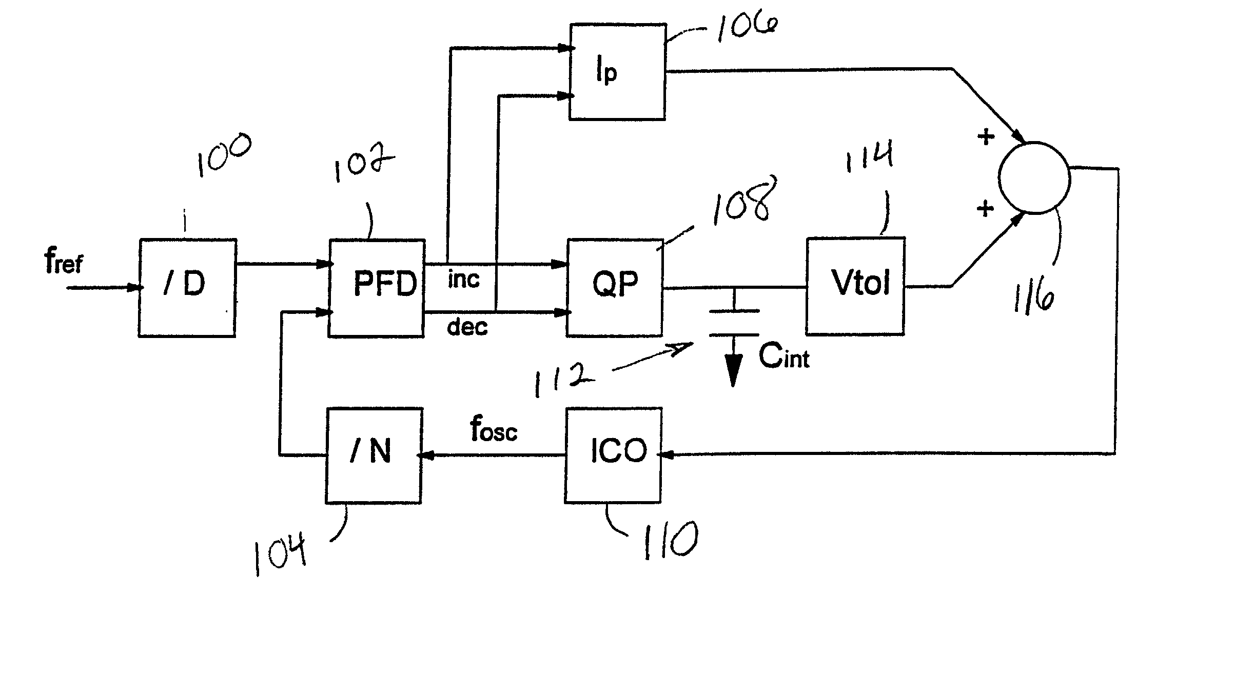
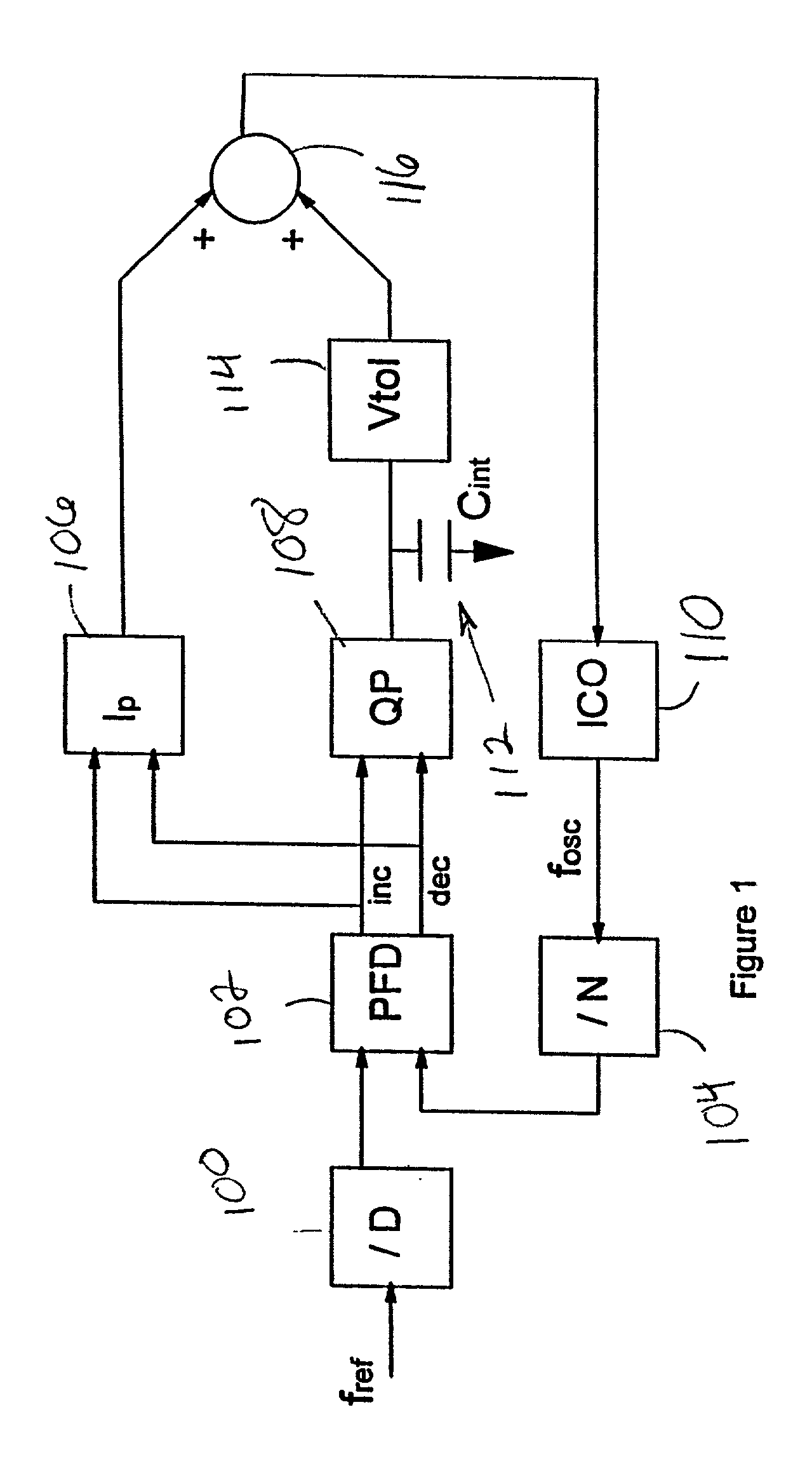
[0021] A first embodiment of the invention is shown in FIG. 1. The frequency synthesizer in FIG. 1 includes a current controlled oscillator (ICO) 110, N and D frequency dividers 104, 100, phase-frequency detector (PFD) 102, and a proportional-integral (PI) loop filter. The PI filter includes a charge pump (QP) 108, integration capacitor (Cint) 112, voltage-to-current converter (VtoI) 114, and proportional correction (Ip) 106. The output of the proportional path 106 is summed with the output of the integral path or VtoI 114 by the summation unit 116. The summed current from the summation unit 116 is input to the ICO 110. The synthesized oscillator frequency f.sub.osc, is a rational multiple N / D of the input reference frequency, f.sub.ref.

[0022] The input signal f.sub.ref is divided by D frequency divider 100 to produce signal f.sub.ref / D The oscillator signal f.sub.osc is divided by N frequency divider 104 to produce signal f.sub.osc / N. Signals f.sub.ref / D and f.sub.osc / N are inputs ...


PUM


Abstract

A frequency synthesizer includes a charge pump, a fractional integration counter that alters the integrated current of the charge pump, a phase frequency detector, a proportional correction circuit, and a proportional multiplier that alters the value of the current correction output by the proportional correction circuit. The fractional integration counter alters the integrated current of the charge pump based upon a user-defined input, thereby permitting increased signal-to-noise ratio at the output of the charge pump. Similarly, the proportional multiplier alters the value of the proportional current correction based upon user-defined input, thereby modifying loop dynamics within the frequency synthesizer.

Description

[0001] 1. Field of the Invention[0002] The present invention generally relates to a frequency synthesizer and more particularly to an improved circuit for controlling loop dynamics of the frequency synthesizer.[0003] 2. Description of the Related Art[0004] Conventional systems utilize frequency synthesizers for a wide range of purposes. For example, frequency synthesizers are used in computer storage systems (such as optical, magnetic, and the like). In order to record digital data onto the surface of a storage medium, which is typically in the form of a rotating magnetic or optical disk, surface characteristics of the disk are modified. Digital data modulates the operation of a write transducer (write head) which records binary sequences onto the disk in radially concentric or spiral tracks. In magnetic recording systems, for example, the digital data modulates the current in a write coil in order to record a series of magnetic flux transitions onto the surface of a magnetizable di...

Claims


Application Information

Patent Timeline
IPC IPC(8): H03L7/089H03L7/18
CPCH03L7/18H03L7/0893
Inventor MASENAS, CHARLES J.PERRI, ANTHONY J.SEMAN, TROY A.
Owner GLOBALFOUNDRIES US INC
Why Eureka
Try Eureka