

Vehicle blower unit
a technology of blower unit and blower body, which is applied in the direction of positive displacement liquid engine, piston pump, liquid fuel engine, etc., can solve problems such as whiz nois
- Summary
- Abstract
- Description
- Claims
- Application Information
AI Technical Summary
Benefits of technology
Problems solved by technology
Method used
Image

Examples
first embodiment
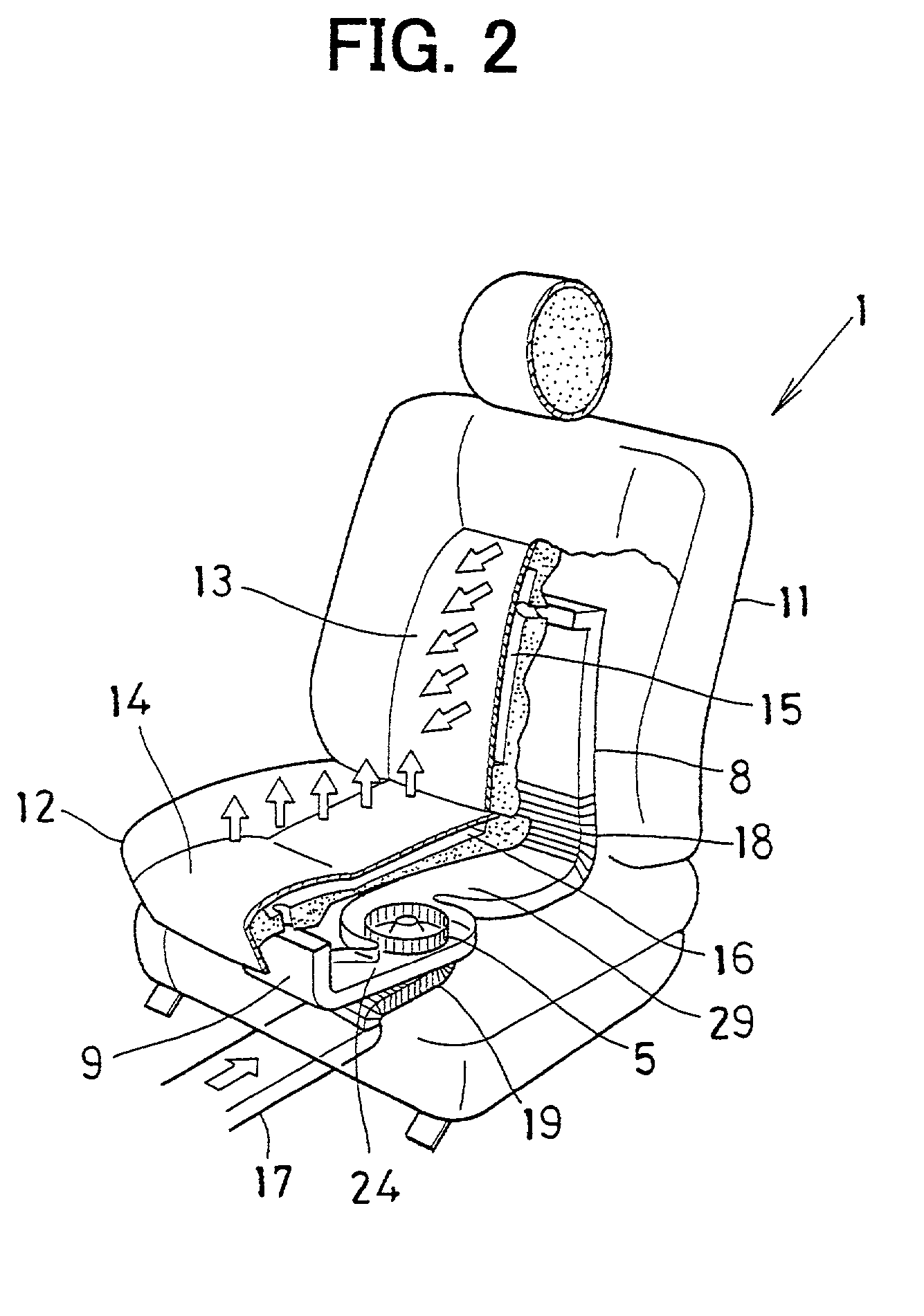
[0063] Next, the operation of the vehicle seat air conditioner will be now described. A PWM control signal, that is set at a duty ratio for obtaining an air amount (target rotational speed) corresponding to the set position of the seat air volume setting controllers (variable resistors) 51, 52 on the driver's seat side and the front passenger's seat side, is input to each of the motor drive circuits 7 on the driver's seat side and the front passenger's seat side from the air conditioning ECU 50. Then, the plural switching devices of the respective motor drive circuits 7 are operated in sequence to pass a current through the three-phase armature windings 41 to 43 of the brushless flat motor 6.
[0064] For example, when the current passes in sequence through the three-phase armature windings 41 to 43 so as to change the electric angle by a phase difference of 120.degree., a rotating magnetic field is generated in the brushless flat motor 6. By controlling this rotating magnetic field i...
second embodiment
[0074] the present invention will be now described with reference to FIGS. 6-8.
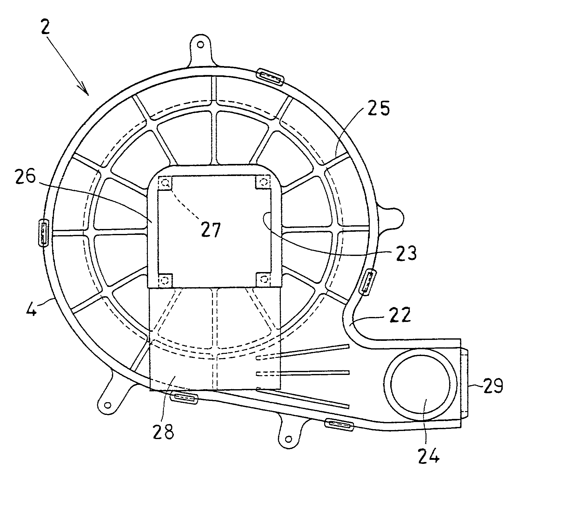
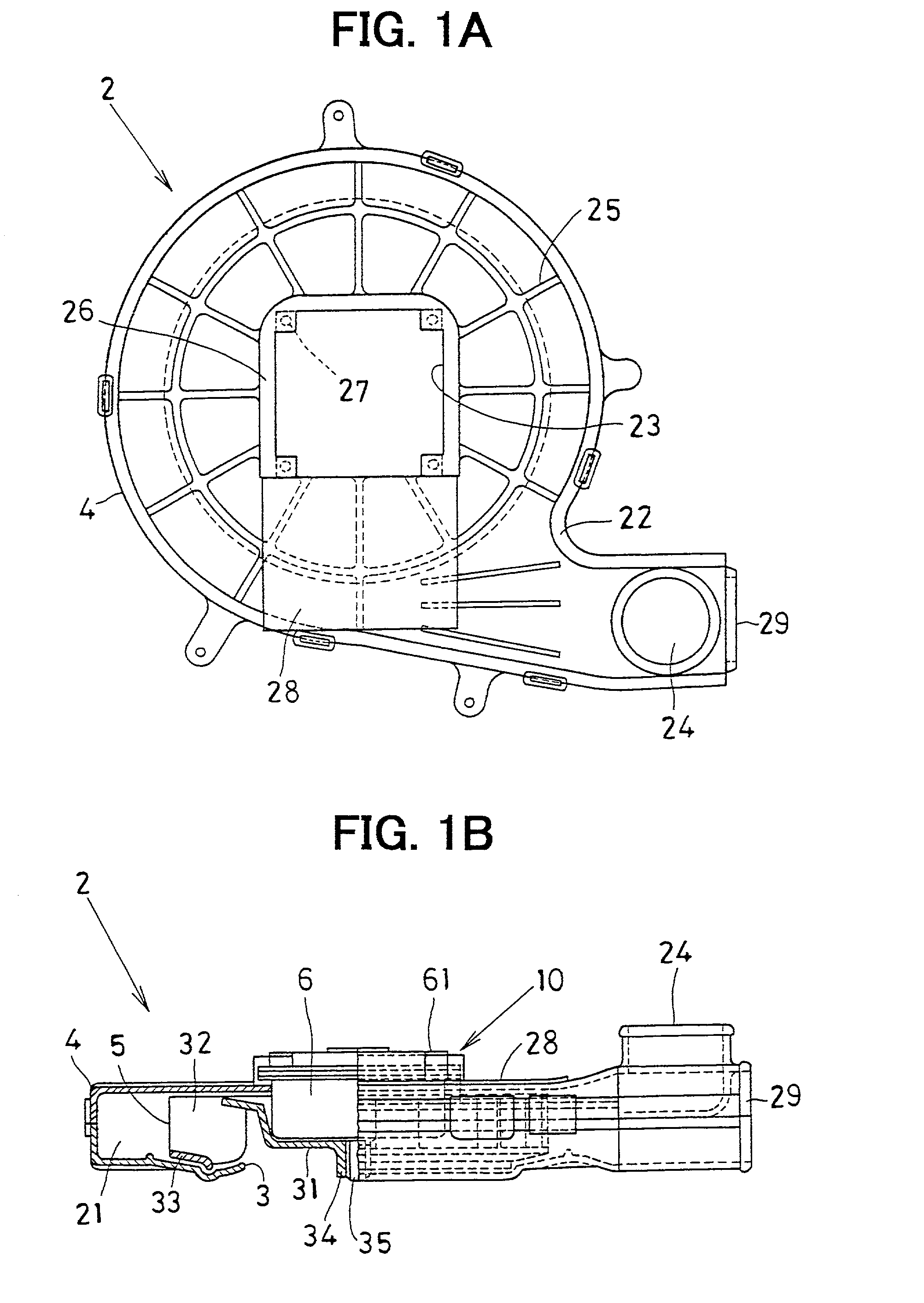
[0075] In the second embodiment, an air conditioning duct is constructed by a movable duct 19 connected to a downstream air side of a seat air blowing duct 17, and a unit case 4 having an air suction port 3 at a downstream air end of the movable duct 19, as shown in FIGS. 6 and 7A. A motor drive circuit 70 of the second embodiment is disposed in an analog circuit 74 to which an analog signal is applied from seat air volume setting controllers (variable resistors) 71, 72 via a motor control circuit 73. The air volume setting controllers 71, 72 are for setting the volume of conditioned air blown to the surfaces of front seats 1 on a driver's side and a front passenger's seat side, respectively. Incidentally, a voltage signal (analog signal) VCD is applied to the motor control circuit 73 from the seat air volume setting controllers 71, 72. In FIG. 7B, S5 indicates a power voltage of 5V, and IG denotes an ign...
fourth embodiment
[0096] The centrifugal fan 305 is constituted by a bottom plate 314 to which the rotational force of a brushless flat motor 306 is transmitted, plural blades 315 fixed to the outer peripheral end portion of the bottom plate 314, an annular holding ring 316 for holding the respective blades 315. In the bottom plate 314, the outer rotor 45 of the brushless flat motor 306 is fitted. Further, the brushless flat motor 306 is a DC brushless motor provided with a stator core, a stator, and the outer rotor 45, similarly to the above-described
[0097] The motor drive circuit 307 has a circuit structure similar to, for example, that of the motor drive circuit 7 shown in FIG. 9, and is constituted, in particular, by a power transistor for controlling a large current and a MOS-FET constituting a plurality of switching devices. The motor drive circuit 307 is placed on a circuit board 57 fixedly fastened to the bottom surface, in the drawing, of the motor attachment bracket 310. Incidentally, the h...
PUM
 Abstract
Description
Claims
Application Information