Structural timber floor assembly

a technology of structural timber and floor boards, applied in the direction of walls, floors, building components, etc., can solve the problems of significant bending and shearing force on the joints between the component parts, weakened flooring panels, and twisting and distortion of panels

Inactive Publication Date: 2002-10-24
MARLOW
View PDF0 Cites 4 Cited by
  • Summary
  • Abstract
  • Description
  • Claims
  • Application Information

AI Technical Summary

Problems solved by technology

However the handling of such flooring panels or decks, after prefabrication, during storage, shipping from factory to site, and when lifted (usually by crane) into position at first floor level, can result in twisting and distortion of the panels, generating significant bending and shearing forces on the joints between the component parts.
The re...

Method used


Image

  • Structural timber floor assembly
  • Structural timber floor assembly
  • Structural timber floor assembly

Examples


Embodiment Construction

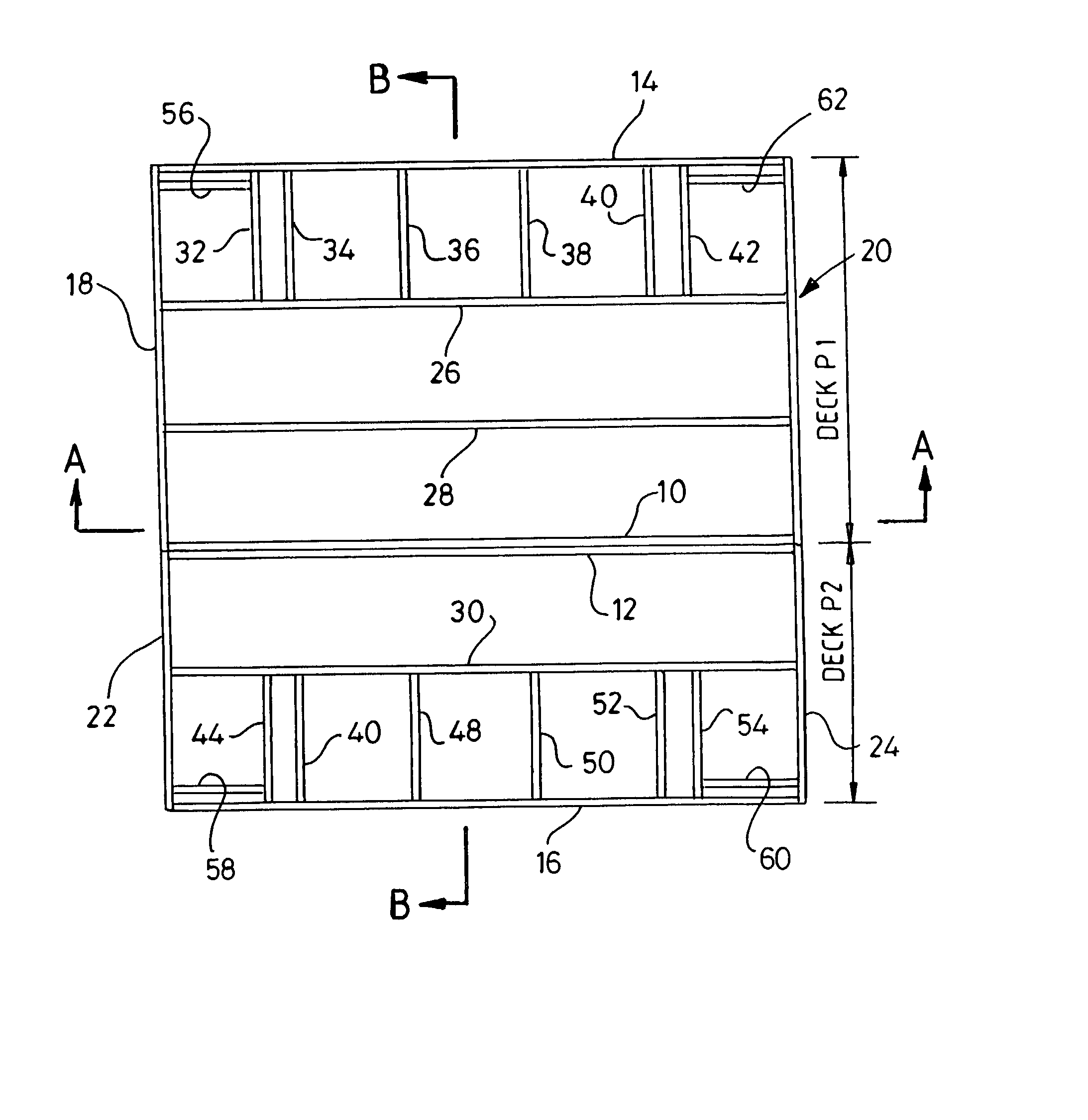
[0037] In FIG. 1 a timber I-beam joist 10 is shown formed from a relatively thin vertical web of timber / timber composite material 12, the upper and lower longer edges of which are adhesively bonded into routed grooves in the upper and lower flanges or rails 14, 16 each of which is formed by laminating a larger number of thin strips of timber, the laminations running parallel to the length dimension of the beam (as shown) and the stack being orientated generally at right angles to the web 12. The laminations are denoted by reference numeral 18 in the case of the upper flange 14 and by 20 in the case of the lower rail 16.

[0038] The end of the beam is cut square so that the cut ends 22, 24 of the upper and lower rails occupy the same plane as does the cut end 26 of the web 12.

[0039] A timber rim joist 28 is to be butt-joined to the end faces 22, 24, 26 of the I-beam joist 10.

[0040] In accordance with the invention holes are formed in the upper and lower rails (only the upper one 30 bei...


PUM


Abstract

A method is described of forming a joint between the end of a timber I-beam joist and a transverse closure such as a rim-joist, in which two holes are formed a short distance from the end of the I-beam to be butt-jointed to the rim-joist, one in each of the upper and lower rails of the I-beam section, the two holes being coaxial and generally aligned with and parallel to the web of the I-beam section. The closure is positioned relative to the I-beam and two further holes are formed through the closure and into the ends of the upper and lower I-beam rails, generally perpendicular to and intersecting the first two holes. Two cross-dowels are inserted into the two first holes, each having a transverse threaded opening, and the dowels are inserted so as to align the openings with the holes which intersect the holes containing the cross-dowels, and threaded bolts are introduced into the intersecting holes and screwed into the threaded openings in the cross-dowels so as to draw the joist towards the closure, and thereby clamp the joist thereto. The cross-dowels may be formed from metal, or from a rigid plastics material or from a composite material and may have a smooth exterior or may be externally threaded or formed with one or more annular barbs for securing them in place. The technique may be applied on site, but more preferably in the course of constructing a roofing or flooring panel off-site, the joints serving to resist distortion or bending during handling of prefabricated panels, during storage, transportation, and/or final positioning on site.

Description

[0001] This invention concerns structural assemblies of timber which serve as prefabricated roofs or floors (often referred to as decks) for buildings, particularly but not exclusively, timber framed buildings.BACKGROUND TO THE INVENTION[0002] Prefabricated timber buildings are generally delivered to site in the form of prefabricated wall panels and roof trusses. The ground floor wall panels, when erected, provide load-bearing supports for first-floor flooring, the peripheral regions of which will in general provide a bearing for the first floor load bearing wall panels.[0003] Timber I-beams are now used in the construction industry as an alternative to solid timber beams, and comprise a thin vertical web, typically made from oriental strand board, and top and bottom chord members (rails or flanges) made from solid or laminated timber. The I-beam section is more structurally efficient than a solid rectangular section and can be made to larger dimensions than is available in solid ti...

Claims


Application Information

Patent Timeline
IPC IPC(8): E04B5/12E04B5/48
CPCE04B5/48E04B5/12
Inventor SMITH, ROGER
Owner MARLOW
Why Eureka
Try Eureka