Electroactive apparatus and methods

Inactive Publication Date: 2002-10-24
CLEMSON UNIVERSITY
View PDF13 Cites 12 Cited by
  • Summary
  • Abstract
  • Description
  • Claims
  • Application Information

AI Technical Summary

Problems solved by technology

In the manufacture of stress-biased electroactive devices, dome formation can occur in the device due to thermal expansion mismatch between layers of different materials that are bonded together or due to internal asymmetrical biases created in a single layer of the device.
In addition, the level of pre-load can impact the total displacement capabilities of the electroactive device.
As can be seen, in general, an increased pre-load force applied to the device leads to an increase in total free displacem

Method used


Image

  • Electroactive apparatus and methods
  • Electroactive apparatus and methods
  • Electroactive apparatus and methods

Examples


example 2

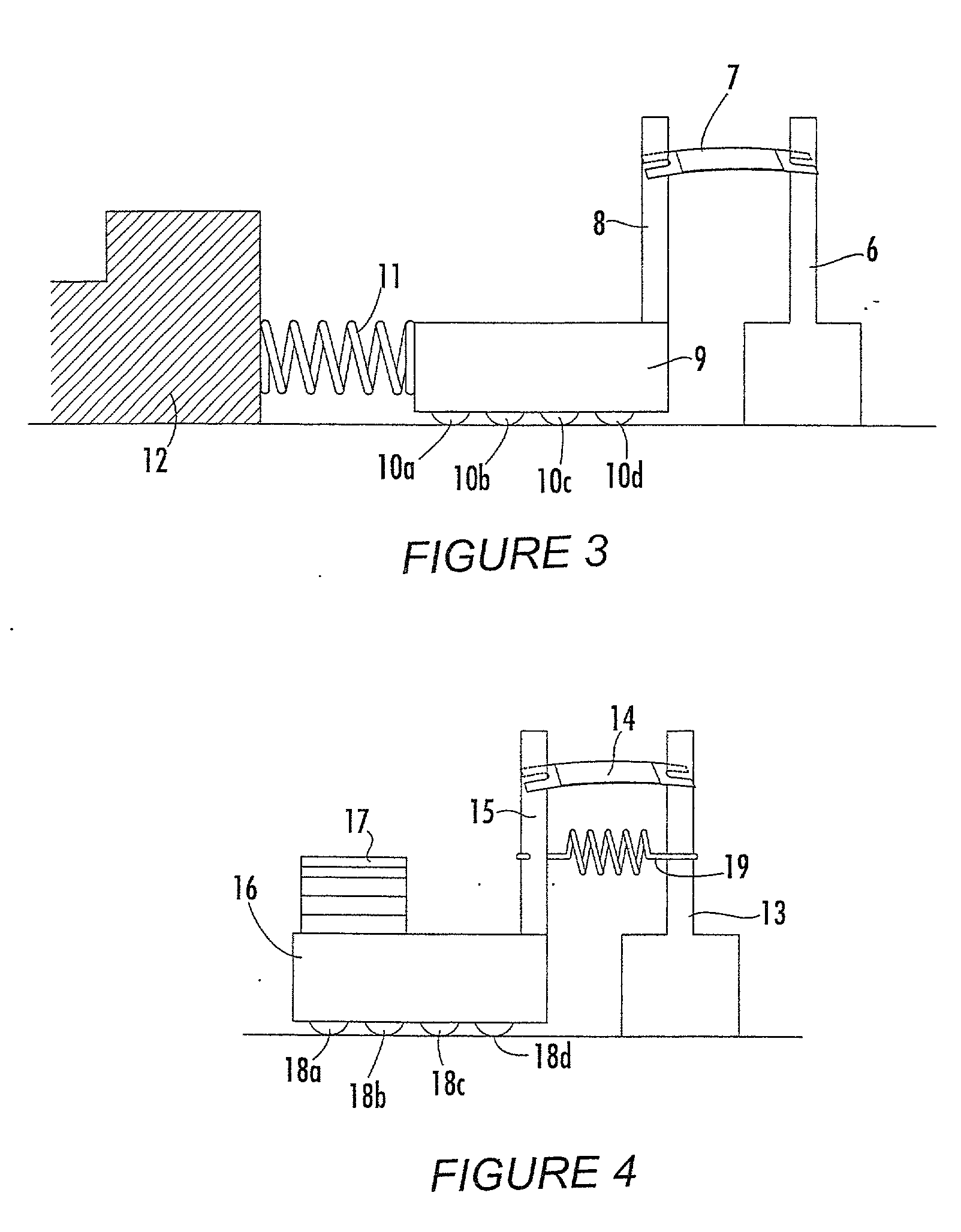
[0100] A THUNDER.RTM. actuator similar to that of Example 1 was placed between two posts. A mechanical pre-load was applied to the actuator by mounting an extended spring (FIG. 4, 19) between the two posts upon which the actuator was mounted, similar to that shown by the structure of FIG. 4. The actuator was held in place between the two poles by the force applied to the system from the spring. Different devices were prepared with various pre-loads ranging between about 2 and about 4 Newtons acting on the actuator in its static equilibrium condition. The same voltage as in Example 1 was applied to the modified systems.

[0101] The measured responses can be seen in FIG. 8. The total response varied between about 0.2 and about 2.5 mm depending upon the drive frequency. The addition of the mechanical pre-load to the actuator due to the tensioning device (i.e. spring) increased actuator performance or electromechanical response over that of the prior art device across most of the frequenc...

example 3

[0103] FIG. 9 graphically illustrates the benefits of adding a mechanical pre-load to an electroactive composite structure when the structure has been loaded with an applied mass. The device provides work through movement of the mass in a vertical direction when an electrical voltage is applied across the electroactive structure.

[0104] Similar electroactive devices and voltage conditions were prepared as described in Examples 1 (standard device) and 2 (spring modified device), above. A 100 g mass was placed on the top center of the electroactive device prior to voltage application. A drive voltage of about 200 volts was applied to the devices over a frequency range of from about 0 to about 30 Hz.

[0105] As can be seen in FIG. 9, a maximum displacement of about 0.37 mm was observed for the standard device, while the modified device displayed a displacement of more than about 0.65 mm. The addition of the mechanical pre-load to the electroactive composite structure provided an improved ...


PUM


Abstract

High performance electromechanical devices suitable for a wide range of applications are described. The electroactive devices are capable of operating in a manner that offers enhanced mechanical displacement responses and increased load-bearing capabilities. In one embodiment, the device is capable of providing a significantly increased level of free displacement. The electroactive devices include an electroactive composite which includes at least one electroactive material that may comprise an electrostrictive or a piezoelectric material and a tensioning device which is adapted for inducing a mechanical pre-load to the electroactive composite structure. The tensioning device exerts a mechanical pre-load upon the electroactive material which alters stress profile, increases mechanical energy and increases stored elastic energy of the electroactive devices.

Description

[0001] This application claims priority to an earlier filed provisional U.S. patent application Serial No. 60 / 286,131 filed Apr. 24, 2001 entitled "Electroactive Apparatus and Methods".[0002] Electroactive composites include piezoelectric and electrostrictive materials. Piezoelectric and electrostrictive materials are those materials which produce dimensional changes when under the influence of an electrical field. Conversely, when put under stress conditions, piezoelectric materials can develop an electrical field, or in open circuit conditions, a polarization.[0003] Conventional, non-stress-biased electroactive devices exhibit relatively limited mechanical displacements when an electric field is applied. These devices can be generally described as electroactive structures which include at least one piezoelectric or electrostrictive material attached or bonded to at least one other material which can operate as an electrode, support layer, strain amplification material, or the like...

Claims


Application Information

Patent Timeline
IPC IPC(8): H01L41/053H01L41/09
CPCH01L41/053H01L41/098H01L41/0933Y10S310/80H10N30/886H10N30/204
Inventor SCHWARTZ, ROBERT W.NARAYANAN, MANOJ
Owner CLEMSON UNIVERSITY
Why Eureka
Try Eureka