Reproducing apparatus

a technology recording medium, which is applied in the field of information reproducing apparatus, can solve the problems of unable to implement suitable waveform equalization for optical disc, relatively complicated signal processing by the decider, and relatively complicated error calculation process

Inactive Publication Date: 2002-10-24
JVC KENWOOD CORP A CORP OF JAPAN
View PDF2 Cites 2 Cited by
  • Summary
  • Abstract
  • Description
  • Claims
  • Application Information

AI Technical Summary

Benefits of technology

0010] It is an object of this invention to provide an improved reproducing apparatus.

Problems solved by technology

Accordingly, the apparatus of Japanese patent application 10-106161 fails to implement suitable waveform equalization for an optical disc which lacks such predetermined pits.
Since the decider includes the two comparators, the signal processing by the decider and also an error calculation process are relatively complicated.

Method used


Image

  • Reproducing apparatus
  • Reproducing apparatus
  • Reproducing apparatus

Examples


first embodiment

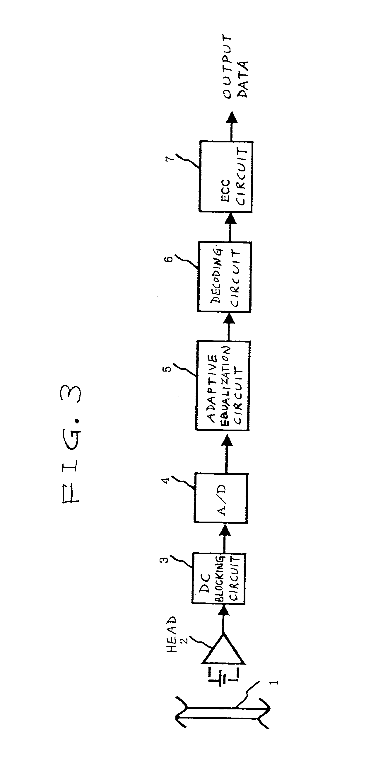
[0033] FIG. 3 shows an information reproducing apparatus according to a first embodiment of this invention. With reference to FIG. 3, an optical disc 1 stores a signal of a run-length-limited code at a predetermined high recording density. An optical head 2 reads out the signal of the run-length-limited code from the optical disc 1. The optical head 2 includes a photoelectric converter (a photodetector), and an amplifier following the photoelectric converter. The optical head 2 outputs the read-out signal to a direct-current blocking circuit (a DC blocking circuit) 3.

[0034] The circuit 3 blocks a direct-current component (a DC component) of the read-out signal, and passes only alternating5 current components (AC components) thereof. The output signal of the DC blocking circuit 3 is applied to an A / D (analog-to-digital) converter 4. The A / D converter 4 changes the output signal of the DC blocking circuit 3 into a corresponding digital signal.

[0035] Specifically, the A / D converter 4 r...

second embodiment

[0057] A second embodiment of this invention is similar to the first embodiment thereof except that an adaptive equalization circuit 5B replaces the adaptive equalization circuit 5 (see FIGS. 3 and 4).

[0058] As shown in FIG. 7, the adaptive equalization circuit 5B includes a demultiplexer 57, a multiplexer 58, and first and second filter sections 5Ba and 5Bb connected between the demultiplexer and the multiplexer 58. The first filter section 5Ba has D-FFs 56a and 56b, multipliers 52d, 52e, and 52f, an adder 53a, a temporary decision device (a provisional determination device) 54a, and a coefficient updating device 55a. The second filter section 5Bb has D-FFs 56c and 56d, multipliers 52g, 52h, and 52i, an adder 53b, a temporary decision device 54b, and a coefficient updating device 55b.

[0059] The demultiplexer 57 receives the output signal of the A / D converter 4, that is, a sequence of digital samples (signal samples). Alternatively, the demultiplexer 57 may receive a signal resultin...

third embodiment

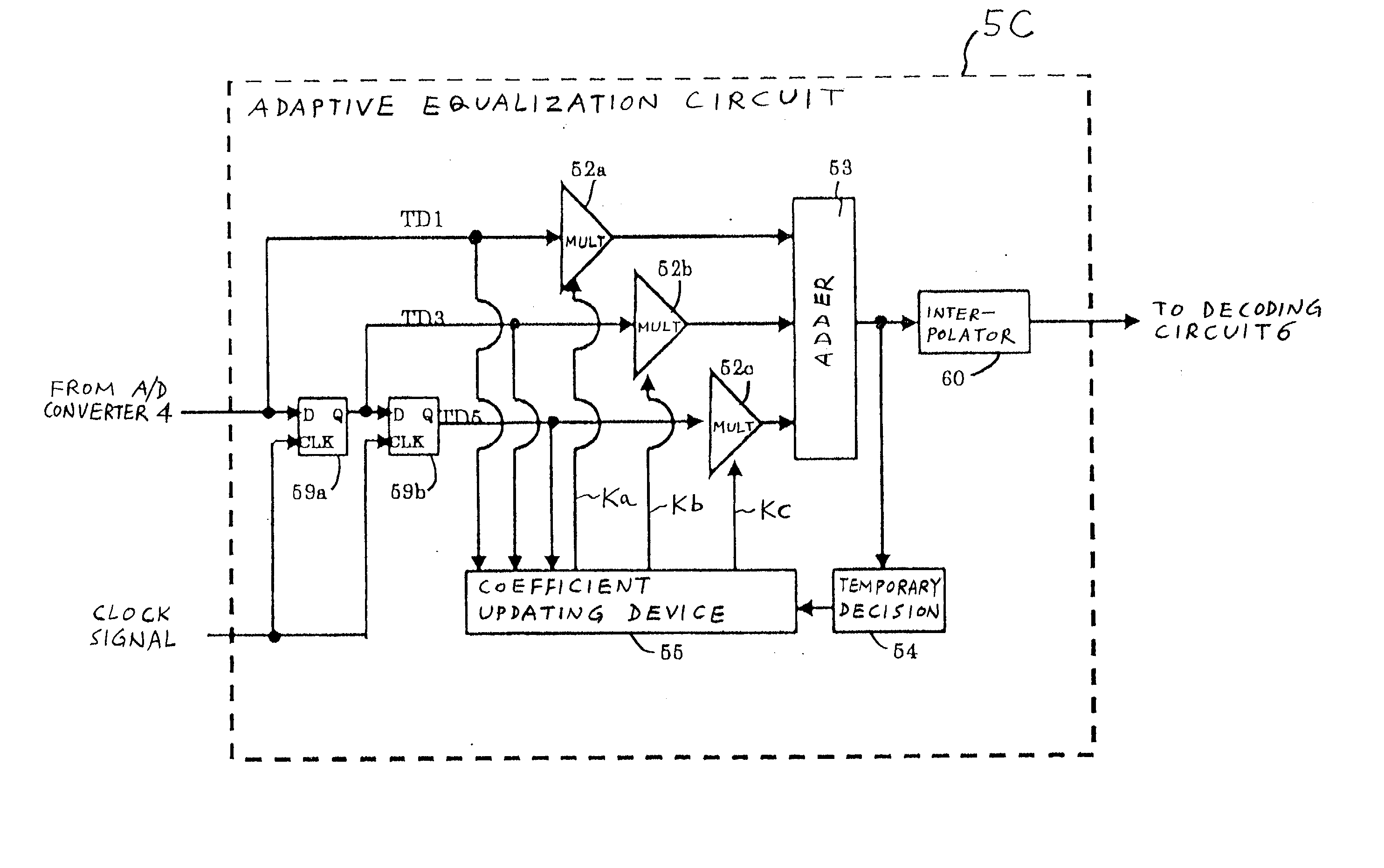
[0074] A third embodiment of this invention is similar to the first embodiment thereof except that an adaptive equalization circuit 5C replaces the adaptive equalization circuit 5 (see FIGS. 3 and 4). As shown in FIG. 8, the adaptive equalization circuit 5C includes D-FFs 59a and 59b, multipliers 52a, 52b, and 52c, an adder 53, a temporary decision device (a provisional determination device) 54, a coefficient updating device 55, and an interpolator 60.

[0075] The D-FFs 59a and 59b, the multipliers 52a, 52b, and 52c, and the adder 53 are connected to form a transversal filter. Specifically, the D-FFs 59a and 59b are connected in cascade or series in that order to compose a multiple-tape delay line in the transversal filter. The input terminal of the D-FF 59a is subjected to the output signal of the A / D converter 4. Alternatively, the input terminal of the D-FF 59a may be subjected to a signal resulting from re-sampling the output signal of the A / D converter 4 on an interpolation basis...


PUM

PropertyMeasurementUnit
run-lengthaaaaaaaaaa
information recording densityaaaaaaaaaa
frequencyaaaaaaaaaa

Abstract

A signal is reproduced from a recording medium. The reproduced signal is sampled in response to a clock signal to get a sampling-resultant signal. A transversal filter includes a delay line having taps and delaying the sampling-resultant signal, multipliers for multiplying only alternate ones among signals appearing at the taps by tap coefficients to get multiplication results, and an adder for adding the multiplication results into a filtering-resultant signal. A temporary decision device operates for calculating a temporary decision value of the filtering-resultant signal according to a temporary decision procedure, for calculating a difference between the temporary decision value of the filtering-resultant signal and an actual value thereof, and for generating an error signal in response to the calculated difference. The tap coefficients used in the transversal filter are controlled in response to the error signal and the reproduced signal to minimize the error signal.

Description

BACKGROUND OF THE INVENTION[0001] 2. Field of the Invention[0002] This invention generally relates to an apparatus for reproducing information from a recording medium. This invention specifically relates to an information reproducing apparatus including a waveform equalization circuit for processing a signal reproduced from a recording medium such as an optical disc.[0003] 2. Description of the Related Art[0004] Japanese patent application publication number 10-106161 / 1998 discloses an optical information reproducing apparatus based on a PRML (partial response maximum likelihood) system. In the apparatus of Japanese patent application 10-106161, information of a run-length-limited code is reproduced from an optical disc through a reproducing section, and a transversal filter subjects the reproduced waveform to partial-response equalization.[0005] The output signal of the transversal filter is decoded into binary data by a maximum-likelihood decoder. The apparatus of Japanese patent ...

Claims


Application Information

Patent Timeline
Patent Type & Authority Applications(United States)
IPC IPC(8): G11B7/005G11B20/10
CPCG11B20/10009G11B20/10037G11B20/10046
Inventor TONAMI, JUNICHIRONAKAMURA, HIDEKI
Owner JVC KENWOOD CORP A CORP OF JAPAN
Why Eureka
Try Eureka