Liquid fuel-reforming process

a liquid fuel and process technology, applied in the field of liquid fuel re-reform process, can solve the problems of critical problems, significant increase in consumption of fuel oils, and important depletion of oil resources, so as to improve the combustion efficiency of internal combustion engines and reduce exhaust pollution

Inactive Publication Date: 2002-10-24
OKADA MASAO
View PDF0 Cites 6 Cited by
  • Summary
  • Abstract
  • Description
  • Claims
  • Application Information

AI Technical Summary

Benefits of technology

0006] It is therefore an object of the present invention to a oil fuel-reforming process that makes it possible to improve combustion-efficiency of internal-combustion engines used for automobiles, marines, airplanes, thermal power generators, boilers, burning appliances for heating systems, or the like and burning equipment, thereby reducing exhaust pollution gases such as free carbons, NOx, SOx and the like resulting from combustion of the oil fuels. The oil fuel used herein includes gasoline, light oil, heavy oil and other liquid fuels

Problems solved by technology

Recently, depletion of oil resources comes up as an important problem because of recent enormous amount of consumption of oil fuels.
In addition, there are problems for immediate solutions including greenhouse reduction and so-called purification of pollution exhaust-gases such as carbon dioxide, nitrogen oxides (NOx), sulfur oxides (SOx), free-carbons, unburned hydrocarbons that result from consumption of mineral oil or imperfect combustion of mineral oils.
In particular, the consumption of fuel oils is increased remarkably because of considerably increase in total number of automobiles, which in turn causes critical problems viewed in the light of health care.
However, such a metal catalyst contains metal such as harmful lead or zinc, resulting in environmental pollution due to the harmful metal contained in the auto exhausts.
Thus, the approach had fallen into disuse.
If such a radioactive catalyst is put in a fuel tank of each automobile for a long period of time, there is a fear of radioactive leakage.
In addition, the fuel in the tank may be contaminated with a small amount of the powdered radioactive catalyst and the exhausted gas may contain some amount of the powdered radioactive catalyst, resulting in environmental pollution.
In particular, places where a large number of automobiles are concentrated, there is a fear of second pollution by radioactivity.

Method used


Image

  • Liquid fuel-reforming process
  • Liquid fuel-reforming process
  • Liquid fuel-reforming process

Examples


Embodiment Construction

[0034]

1 Glucose 100 parts by weight Sterilized water 1000 parts by weight potassium phosphate 1 part by weight Urea 1 part by weight Sodium chloride (or sodium sulfate) 0.5 parts by weight

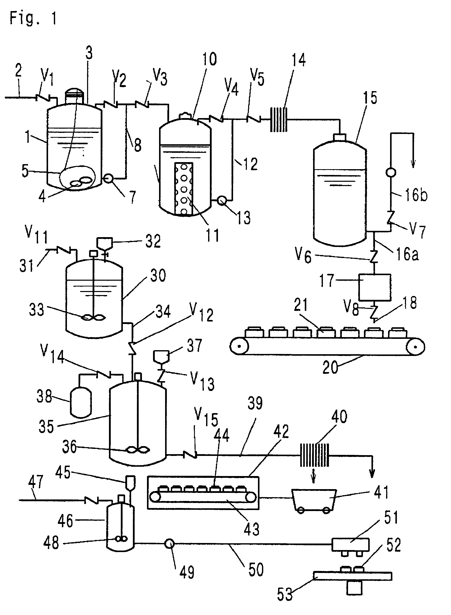
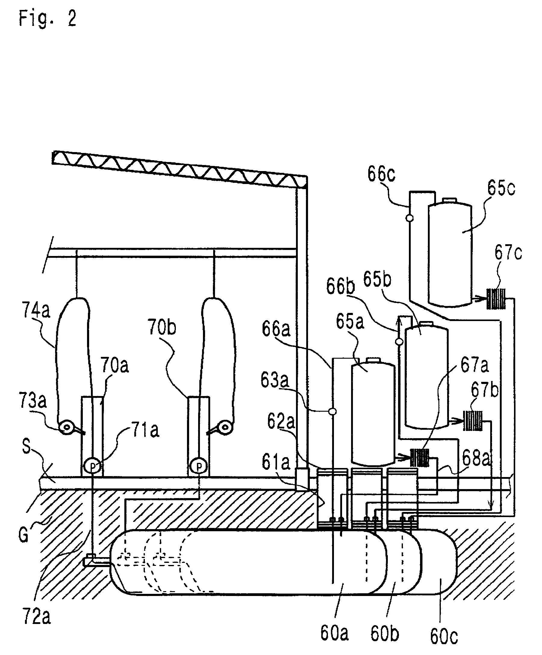
[0035] The oil fuel, e.g., gasoline (F) in the tank 60a is pumped up from the fuel tank 60a by the pump 63 and fed to the culture tank 65a through the line 66a where the oil fuel is brought into contact with the aspergillus fungi. The bacterial catalyst bags were replaced at interval of 6 months with new ones. Then, the oil fuel was supplied to the filter 67a to remove impurities and then returned to the fuel tank 60a through the line 68 to recirculate the system. The circulation of the fuel was continued for about 4 to 6 weeks. During circulation, the hydrocarbons having C16 to C18 in the oil fuel were biologically decomposed into lower hydrocarbons having C6 to C10. The resultant reformed oil fuel in the oil tanks 60a contains activated aspergillus fungi and thus the oil tanks 60a serves as an ad...


PUM

PropertyMeasurementUnit
radioactivityaaaaaaaaaa
combustion-efficiencyaaaaaaaaaa

Abstract

A process for reforming oil fuel comprises the steps of contacting oil fuel with activated aspergillus fungi for a certain period and then mixing the resulting oil fuel with unreformed oil fuel. The reformed oil fuel may be treated with a magnetic catalyst after treatment by the activated aspergillus fungi.

Description

BACKGROUND OF THE INVENTION[0001] The present invention relates to a liquid fuel-reforming process and, more particularly, to a process for reforming oil fuels such as gasoline, diesel fuel, heavy oil and other liquid fuels, that is suitable for reconstruction of gas stations.[0002] Recently, depletion of oil resources comes up as an important problem because of recent enormous amount of consumption of oil fuels. For this reason, measures for reduction of oil resources have been required. In addition, there are problems for immediate solutions including greenhouse reduction and so-called purification of pollution exhaust-gases such as carbon dioxide, nitrogen oxides (NOx), sulfur oxides (SOx), free-carbons, unburned hydrocarbons that result from consumption of mineral oil or imperfect combustion of mineral oils. In particular, the consumption of fuel oils is increased remarkably because of considerably increase in total number of automobiles, which in turn causes critical problems v...

Claims


Application Information

Patent Timeline
Patent Type & Authority Applications(United States)
IPC IPC(8): C10G32/00C12P5/00
CPCC10G32/00Y10S435/913C12P5/00
Inventor TANAKA, HIDEAKI
Owner OKADA MASAO
Why Eureka
Try Eureka