Compensating element

a technology of compensating elements and components, applied in the direction of machines/engines, mechanical equipment, cylinders, etc., can solve the problems of not being able to preassemble with the fuel injector during installation, spherical surfaces, and not being able to adjust tolerances at all

Inactive Publication Date: 2002-10-31
ROBERT BOSCH GMBH
View PDF0 Cites 19 Cited by
  • Summary
  • Abstract
  • Description
  • Claims
  • Application Information

AI Technical Summary

Benefits of technology

[0011] The compensating sleeve of the compensating element is advantageously in the form of a corrugated tube. This is easy to manufacture and allows both a large degree of longitudinal adjustment, and extensive tilting or bending along its longitudinal axis.
[0013] The compensating element advantageously has a sealing ring, which is situated between a step of the receiving borehole and a preformed shoulder of the support segment. Since the contact pressure of the seal is produced by the axial retaining force holding down the fuel injector and compensating element in the borehole, and not by radially squeezing a sealing ring in a borehole, the unit made of the fuel injector and compensating element can therefore be easily assembled and disassembled. The compression of the seal can be advantageously limited by a radial support ring, which surrounds the sealing ring on the outside.
[0015] The service life of the compensating element can be increased in an advantageous manner, when a heat-resistant elastomer, Teflon.RTM., or graphite is used for the sealing ring, between the support segment and the receiving borehole.
[0016] A higher compressibility and bendability, especially of the flexible segment, can be attained using the same dimensions, when spring steel is used for manufacturing the compensating sleeve.
[0017] An advantageous design of the compensating element according to the present invention is achieved, when the diameter of the connecting segment is dimensioned to form an interference fit with the corresponding segment of the fuel injector, when small forces are applied. On one hand, the compensating element can still be slid easily onto the nozzle body, but on the other hand, it forms a preassembled unit with the fuel injector. without any special fastener, the unit already including all of the seals, as well. This simplifies the installation of the fuel injector.

Problems solved by technology

However, this does not at all allow one to adjust the tolerances of the position of the fuel injector in the receiving borehole.
However, it is disadvantageous that the supporting body is expensive to manufacture and requires a precisely manufactured, spherical surface.
In addition, it cannot be preassembled with the fuel injector during installation, and the two cannot be inserted as a unit.
The variant proposed in DE 197 35 665 A1, of forming the spherical surface on the cylinder head itself and thus, obviating a separate component part, has the disadvantage that the spherical surface requiring a high degree of accuracy must be formed in a bore, at the relatively large workpiece for the entire cylinder head.
Therefore, this has disadvantages from the standpoint of production engineering.
It is disadvantageous to have the additional expenditure associated with having several more components, and to have the additional number of connections to be sealed.
Since the intermediate piece requires an increased overall height, it can only be designed to be relatively short.
Therefore, there is the danger of the sealing, rings not being uniformly compressed between the respective sealing surfaces, when the angle is too large.
This can result in leakage.

Method used


Image

  • Compensating element
  • Compensating element
  • Compensating element

Examples


Embodiment Construction

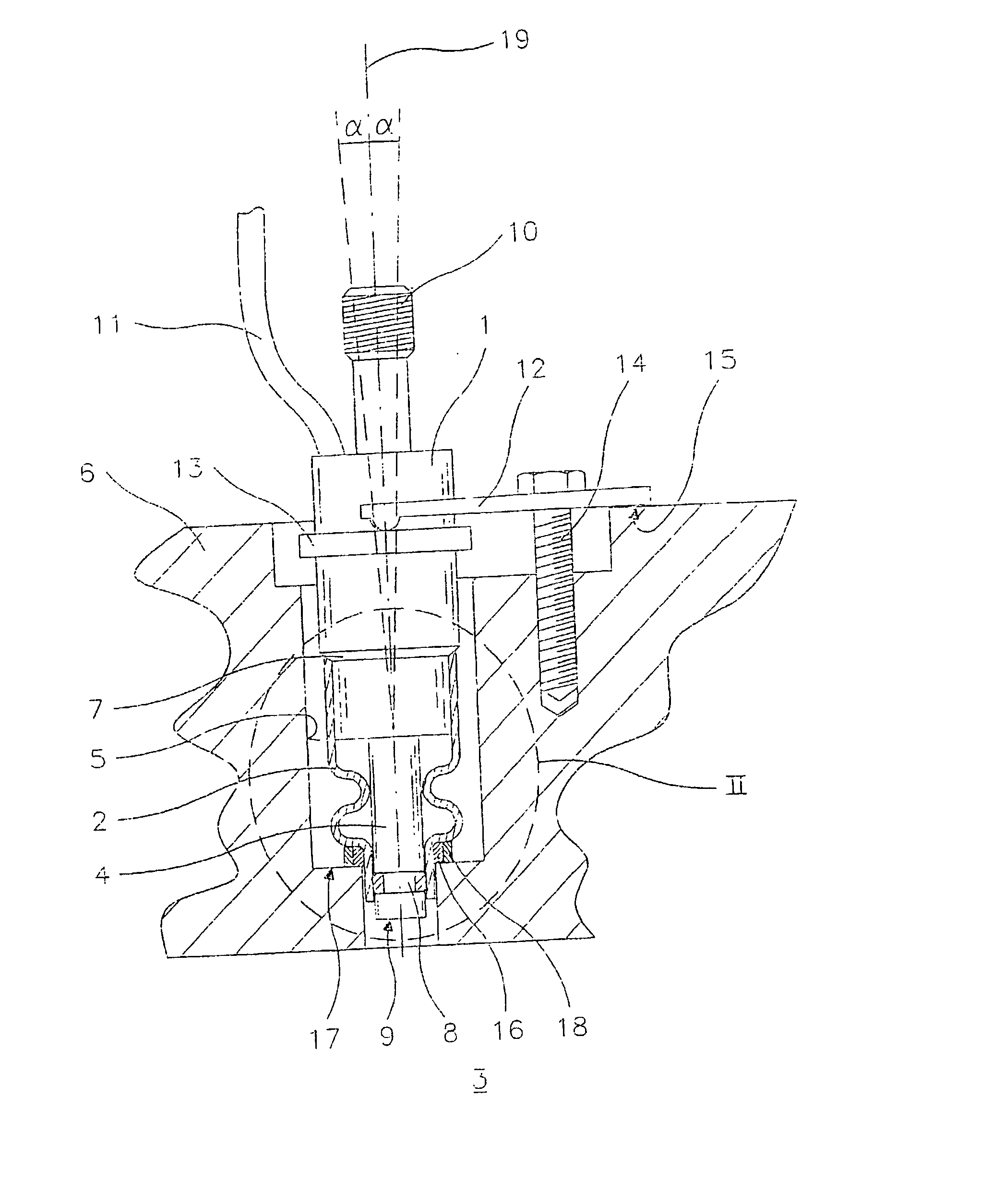
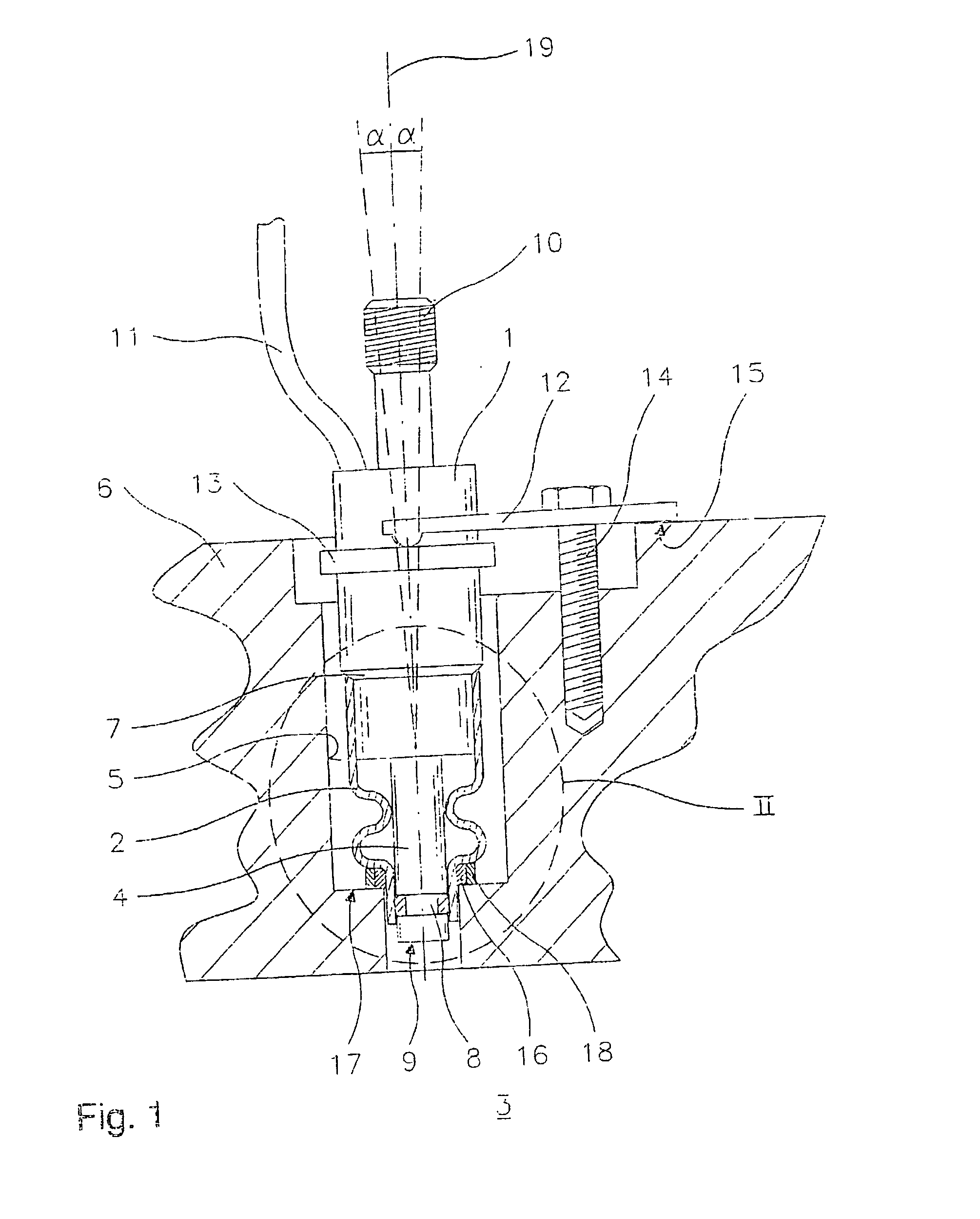
[0021] FIG. 1 shows a partial section of a fuel injector 1 having a compensating element 2 of the present invention. Fuel injection valve 1 is used to inject fuel in a mixture-compressing, spark-ignition engine. The represented valve is a high-pressure injection valve for the direct injection of fuel into combustion chamber 3 of the internal combustion engine. However, compensating element 2 of the present invention can also be used in other cases.

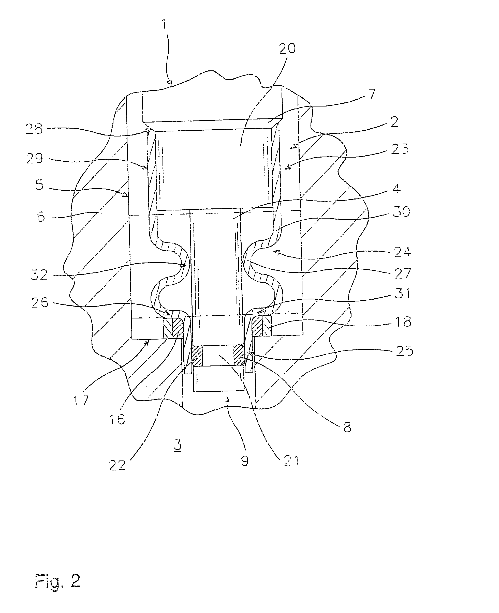
[0022] Fuel injector 1 includes a nozzle body 4 having an ejection-side end 9, and is mounted in a receiving borehole 5 of a cylinder head 6, whose sectional view is indirectly shown. The drawing also shows a first sealing ring 8, which provides a seal between nozzle body 4 and compensating element 2, and may be made out of Teflon.RTM.. At fuel injector 1, the drawing also shows a fuel inlet 10 and a control line 11 for electrically controlled fuel injector 1, which is exemplarily provided here.

[0023] Fuel injector 1 is held in receiving b...


PUM


Abstract

A compensating element (2) for a fuel injector (1), which can be inserted into a receiving borehole (5) of a cylinder head (6) of an internal combustion engine, in order to directly inject fuel into the combustion chamber (3) of the internal combustion engine, has a compensating sleeve (30); a connecting segment (23) of the compensating sleeve (30) being attachable to a housing segment (20) of the fuel injector (1). The compensating element (2) is supported in the receiving borehole (5) of the cylinder head (6), by a support segment (25) of the compensating sleeve (30); and a flexible segment (24) is provided between the connecting segment (23) and the support segment (25).

Description

BACKGROUND INFORMATION[0001] The present invention is based on a compensating element according to the species defined in claim 1.[0002] A thermal protection sleeve is known from DE 197 43 103 A1, which encircles a fuel injector at a nozzle body. The thermal protection sleeve is inserted into a stepped receiving borehole of a cylinder head of an internal combustion engine, and circumferentially surrounds an ejection-side nozzle body segment of a fuel injector inserted into the receiving borehole. One end of the thermal protection sleeve has a collar, which rests against a step of the receiving borehole. In addition, the ejection-side end of the thermal protection sleeve has a folded section, which renders a certain length of the sleeve double-layered. In this region, the sleeve is radially locked between the nozzle body and the bore in the cylinder head. Since a tapered segment of the thermal protection sleeve, against which a correspondingly tapered segment of the fuel injector res...

Claims


Application Information

Patent Timeline
Patent Type & Authority Applications(United States)
IPC IPC(8): F02F1/24F02M53/04F02M61/14
CPCF02M2200/858F02M61/14
Inventor REITER, FERDINAND
Owner ROBERT BOSCH GMBH
Why Eureka
Try Eureka