Casting sand blowing device for molding machines

a molding machine and sand blowing technology, which is applied in the field of molding machines, can solve the problems of large equipment requirements, large loss of pressure during transportation, and large cost of the apparatus for treating gases with a smell, and achieve the effect of simple structur

Inactive Publication Date: 2002-10-31
SINTOKOGIO LTD
View PDF0 Cites 2 Cited by
  • Summary
  • Abstract
  • Description
  • Claims
  • Application Information

AI Technical Summary

Benefits of technology

0005] This invention has been made considering the above-mentioned problems. An object of this invention is to provide a molding machine having a simple structure, wherein the position in a metal mold at which foundry sand is blown thereinto can be easily changed.

Problems solved by technology

Therefore, the conventional blow squeeze apparatus has disadvantages in that the sliding portion has complex structures, a large scale of equipment is needed, and a number of processes are needed to adjust the position at which sand is blown.
Since the means for treating gases with a smell must carry a large volume of the air in addition to the gases from the machines over a long distance, the loss of pressure during the transportation becomes large and the apparatus for treating gases with a smell, including the mechanism for absorbing them, becomes large and costly.

Method used


Image

  • Casting sand blowing device for molding machines
  • Casting sand blowing device for molding machines
  • Casting sand blowing device for molding machines

Examples


Embodiment Construction

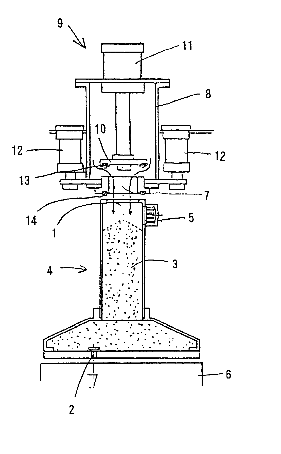
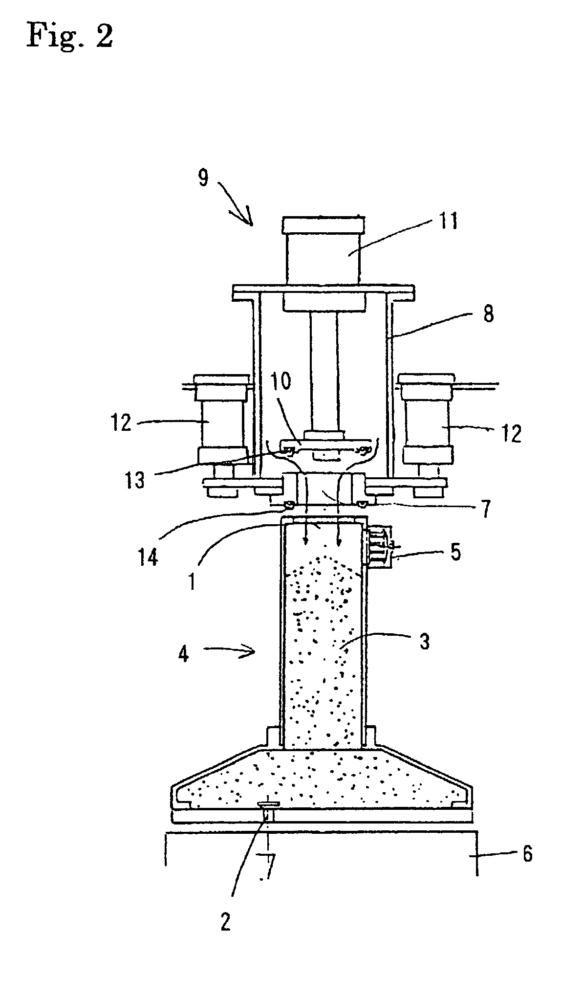
[0019] We now explain a first embodiment of this invention by referring to FIG. 2. The blow-squeeze apparatus comprises a sand tank 4 for storing foundry sand, a compressed-air tank 8 disposed above the sand tank for storing compressed pressure, and means 9 for opening and closing an opening 7 through which foundry sand is blown thereinto.

[0020] The horizontally and vertically movable sand tank 4 comprises an empty chamber 3. A sand-supplying opening 1 and a sand-discharging nozzle 2 are disposed at the upper end and lower end of the sand tank 4, respectively. An exhaust valve 5 for discharging the residual compressed air in the tank is disposed in the upper part of the sand tank 4. The position of the sand-discharging nozzle 2 is made to correspond to a blow-squeeze position, namely, a position at which sand is blown into metal molds 6 (not shown) disposed just under the sand tank 4 for molding a core (as detailed below).

[0021] The compressed-air tank 8, having a discharging openin...


PUM

PropertyMeasurementUnit
pressureaaaaaaaaaa
volumeaaaaaaaaaa
compressed pressureaaaaaaaaaa

Abstract

A blow-squeeze molding apparatus equipped with a compact and cheap gas treating apparatus wherein the loss of pressure in the compressed air is small and the position at which sand is blown into the mold can be easily changed. The apparatus comprises a sand-storing tank equipped with a sand-discharging nozzle and an exhaust valve, a compressed air-storing tank equipped with a compressed air-discharging opening, and means for opening and closing the compressed air-discharging opening. The blow squeeze machine comprises a stationary member for fixing a stationary piece of mold (mold half) and a sliding member for sliding a movable piece of mold. The gas treating apparatus comprises a hood surrounding the shell machine, means for treating gases with a smell, and a guide tube for guiding gases with a smell.

Description

[0001] This invention relates to the improvement in an apparatus for blowing foundry sand into a molding machine for molding a core. It especially relates to molding machines wherein vertically divided metal molds for shell sand or cold-box-process core sand are used, and wherein the position at which sand is blown into molds is changeably constituted. It also relates to a blow squeeze apparatus for a molding machine to which an additional set of equipment is added for treating gases with a smell that are generated when shell sand is fired to prepare dry sand.[0002] As shown in general in FIG. 1, the conventional blow squeeze apparatus is constituted such that a tank 21 for storing sand, a connector 23, an air-supply / exhaust valve 25, and an air tank 27 are connected via a piston rod 22 and conduits 24,26. In the thus-constituted conventional blow-squeeze apparatus, since the distance between the air tank 27 and sand tank 21 is long, the entire apparatus is bulky, a large loss of pr...

Claims


Application Information

Patent Timeline
Patent Type & Authority Applications(United States)
IPC IPC(8): B22C9/12B22C15/24
CPCB22C9/12B22C15/24B22C9/123
Inventor SAKOU, KOJISHIOSE, FUMIKAZU
Owner SINTOKOGIO LTD
Why Eureka
Try Eureka