Method for estimating vehicular running state, vehicular running state estimating device, vehicle control device, and tire wheel

Inactive Publication Date: 2002-11-07
BRIDGESTONE CORP
View PDF18 Cites 62 Cited by
  • Summary
  • Abstract
  • Description
  • Claims
  • Application Information

AI Technical Summary

Problems solved by technology

Meanwhile, in the above method of estimating a road surface friction coefficient from the horizontal-direction vibration of the front wheels having a toe angle, the measurement accuracy is low when the slip angle of the tire is taken completely null or large.
However, as the road surface friction coefficient is estimated from vibration transmission characteristics between two points through a suspension unit having large buffer characteristics such as a spring or damper, the road surface friction coefficient is readily affected by the uneven surface of the road.
For instance, as vibration under a sp

Method used


Image

  • Method for estimating vehicular running state, vehicular running state estimating device, vehicle control device, and tire wheel
  • Method for estimating vehicular running state, vehicular running state estimating device, vehicle control device, and tire wheel
  • Method for estimating vehicular running state, vehicular running state estimating device, vehicle control device, and tire wheel

Examples


embodiment 1

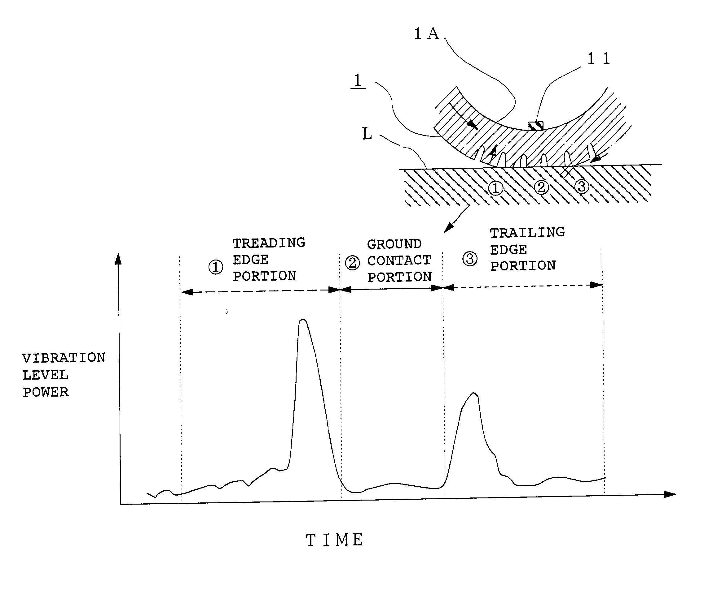
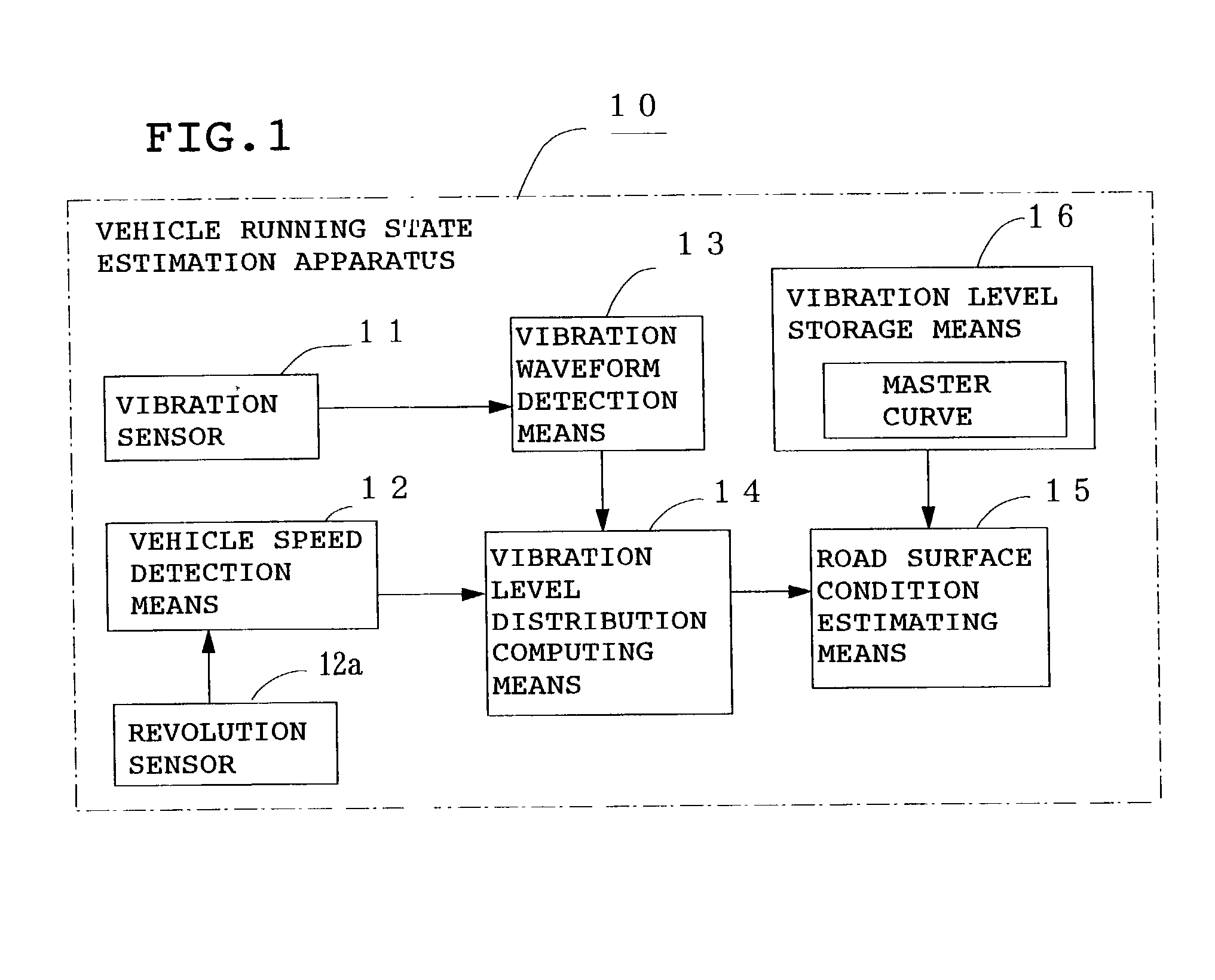
[0098] FIG. 1 is a block diagram showing the constitution of a vehicle running state estimation apparatus 10 of the present invention. In the figure, reference numeral 11 denotes a vibration sensor installed on the inner surface of a tire tread, 12 vehicle speed detection means for detecting vehicle speed based on the output pulse of a revolution sensor 12a for detecting the speed of a wheel, 13 vibration waveform detection means for obtaining the waveform of vibration by arranging the output levels (vibration levels) of the above vibration sensor in time sequence, 14 vibration level distribution computing means for obtaining the vibration level distribution of a tire tread by computing the vibration levels in a leading edge portion, a ground contact portion and a trailing edge portion of the tire using the output pulses of the above revolution sensor 12a, and 15 road surface condition estimation means for estimating the condition of a road surface which is one of the running state...

embodiment 2

[0113] In the above Embodiment 1, the vibration levels of a portion below the spring of the vehicle measured by the vibration sensor 11 are arranged in time sequence by the vibration waveform detection means 13 and the vibration level distribution of the tread 1 is obtained by the vibration level distribution computing means 14 to estimate the condition of a road surface. As shown in FIG. 6, frequency analyzing means 14F for obtaining the frequency spectrum of vibration level obtained by converting the frequency of the above vibration level and vibration level calculating means 14S for calculating a vibration level at a predetermined frequency band of the obtained frequency spectrum are provided in place of the above vibration level distribution computing means 14, and further road surface condition estimation means 15S for estimating the condition of a road surface by comparing the vibration level calculated by the above vibration level calculating means 14S with a master curve for...

embodiment 3

[0118] In the above Embodiment 2, the condition of a road surface is estimated from the vibration level at a predetermined frequency band calculated by the vibration level calculating means 14S. As shown in FIG. 8, vibration level computing means 14 for computing at least two vibration levels at different frequency bands of the obtained frequency spectrum is provided in place of the above vibration level calculating means 14s, and road surface condition estimation means 15S for estimating the condition of a road surface by comparing the computed value of vibration level computed by the above vibration level computing means 14R with a master curve for estimating the condition of a road surface from the frequency spectrum of vibration level stored in the vibration level storage means 16R is provided to estimate the condition of a road surface.

[0119] The above two frequency bands are preferably 300 to 1,000 Hz which is hardly affected by the condition of a road surface and 800 to 5,000...


PUM


Abstract

The output level (vibration level) of vibration of a portion below the spring of a vehicle detected by a vibration sensor mounted to the portion below the spring of the vehicle is frequency converted by frequency analyzing means 14F to obtain the frequency spectrum of the vibration level and an operation is carried out on at least two vibration levels at different frequency bands of the obtained frequency spectrum by vibration level computing means 14R, and this computed value is compared with a master curve showing the frequency spectrum of vibration level stored in vibration level storage means 16S to estimate the condition of a road surface so as to estimate the running state of the vehicle. Further, the running state of each tire including the air pressure of the tire is detected from the vibration level of the portion below the spring of the vehicle to estimate the running state of the vehicle, thereby constructing a multi-function sensing system for estimating the condition of a road surface or the running state of the tire with one sensor.

Description

[0001] 1. Field of the Invention[0002] The present invention relates to a method and apparatus for estimating the running state of a vehicle by estimating the condition of a road surface or the running state of each tire while running, an apparatus for controlling a vehicle based on the estimated running state of a vehicle, and a tire wheel comprising the above vehicle running state estimation apparatus and a power generating unit for activating this apparatus.[0003] 2. Description of the Prior Art[0004] In recent years, it has been desired that the relationship between each tire and the surface of a road which is the most important factor for the safe running of a vehicle, specifically, the ground contact state of the tire typified by a friction coefficient between the tire and the surface of a road (road surface friction coefficient) or the condition of a road surface, or the running state of the tire such as the distortion and air pressure of the tire should be estimated with hig...

Claims


Application Information

Patent Timeline
IPC IPC(8): B60C23/06B60G17/0165B60G17/019B60G17/0195B60T8/172G01H1/00G01H1/12G01H1/14G01N3/06G01N9/24G01N19/02
CPCB60C23/06B60C23/065B60G17/019B60G17/0195B60G2204/11B60G2204/113B60G2400/102B60G2400/204B60G2400/206B60G2400/208B60G2400/52B60G2400/821B60G2400/91B60G2600/02B60G2600/188B60G2600/60B60G2600/604B60G2800/162B60G2800/70B60G2800/702B60G2800/916B60T8/172B60T2210/12B60T2210/13G01H1/003G01H1/12G01H1/14G01N9/24G01N19/02G01N2203/0676G01N2203/0682G01N2203/0688B60G17/0165
Inventor YOKOTA, HIDETOSHIMORINAGA, HIROSHIOTANI, KOJI
Owner BRIDGESTONE CORP
Why Eureka
Try Eureka