Method and device for coating at least one wiper-blade element

a technology of wiper blades and elements, applied in vehicle maintenance, vehicle cleaning, transportation and packaging, etc., can solve the problems of affecting the quality of wiper blades, so as to reduce the risk of rejects, favorable pricing, and positive results

Inactive Publication Date: 2002-11-07
ROBERT BOSCH GMBH
View PDF1 Cites 18 Cited by
  • Summary
  • Abstract
  • Description
  • Claims
  • Application Information

AI Technical Summary

Benefits of technology

0007] According to the invention, the wiper blade element is cut to a usable length from a profiled band before being brought into a treatment chamber, is placed on the electrode plate, and is subjected to a plasma flow.
0008] The individual treatment steps are advantageously executed one after another in a treatment chamber in a so-called single-chamber batch process or in mass quantities in a multiple-chamber batch process with a number of treatment chambers. In a functional manner, a single treatment step is executed in each chamber, where cycle times between the individual treatment steps can be between 10 seconds and several minutes. Cycle times between 30 seconds and 1 minute have turned out to be particularly favorable. The batch process permits the production-critical processes of the rubber shaping and the coating to be decoupled. If malfunctions occur in one manufacturing process, this has no influence on the other manufacturing process. As a result, the risk of rejects is also reduced. In contrast to continuous systems, a coating system with a number of treatment chambers can be embodied in a more favorably priced, flexible manner since a number of similar treatment chambers can be operated in parallel, depending on the treatment duration. This produces particularly positive results if the pretreatment takes place at a slight vacuum of approximately 0.1 to 100 mbar.
0009] The wiper blade elements can be suitably cut from an extruded double-strand profile in which the wiper lips are oriented toward each other and connected to each other via an intermediary piece. One side of the wiper lips rests against the electrode plate. After the first side is coated, the wiper blade element must be turned over inside or outside of the treatment chamber. When the coating is completed, the wiper lips are cut from the intermediary piece. It is also possible to cut the wiper lips apart from each other before the coating.
0010] In a variant of the invention, the wiper blade elements are arranged so that the wiper lips stand approximately perpendicular to the electrode plate, which extends on both sides of the wiper blade element. Thus, both sides of the wiper lip of the wiper blade element can be treated and coated at the same time. A number of wiper blade elements can be arranged next to one another and in series on an electroplate, which represents a part of a merchandise carrier. They can be of different lengths and have different profiles.
0011] The electrode plate suitably engages laterally in longitudinal grooves of the wiper blade element, which are provided for claw brackets or spring strips, so that the wiper blade elements are securely fixed to the electrode plate. This makes a flexible large-scale manufacture possible. Furthermore, cutting processes after coating, which could damage the protective coating, can be eliminated.
0012] The electrode plate suitably has an alternating current applied to it, with a frequency of 10 kHz to a few MHz, preferably 13.56 MHz, where the power to be coupled-in is approximately 1 to 100 W / cm.sup.2 of electrode surface area. Depending on the coupled-in power, the overall pressure, and the surface area ratios, a negative potential (self bias) occurs in the plasma between the electrode plate and ground. This potential engages through the rubber of the wiper blade element and accelerates the ions in the plasma toward the surface of the rubber. This ion bombardment causes a compaction of the coating and thus increases the coating hardness. The effectiveness of the ion bombardment depends on the thickness of the dielectric disposed on the electrode plate, i.e. the thickness of the elastomer material.

Problems solved by technology

The coupling of two critical manufacturing steps, namely of extrusion and coating of the wiper blade element, however, causes the entire production line to come to a halt when there is a breakdown in one part of the manufacturing system and generates a greater amount of manufacturing rejects.
In addition, the protective coating at the ends of the wiper blade element can be damaged in the final cutting procedure.

Method used


Image

  • Method and device for coating at least one wiper-blade element
  • Method and device for coating at least one wiper-blade element
  • Method and device for coating at least one wiper-blade element

Examples


Embodiment Construction

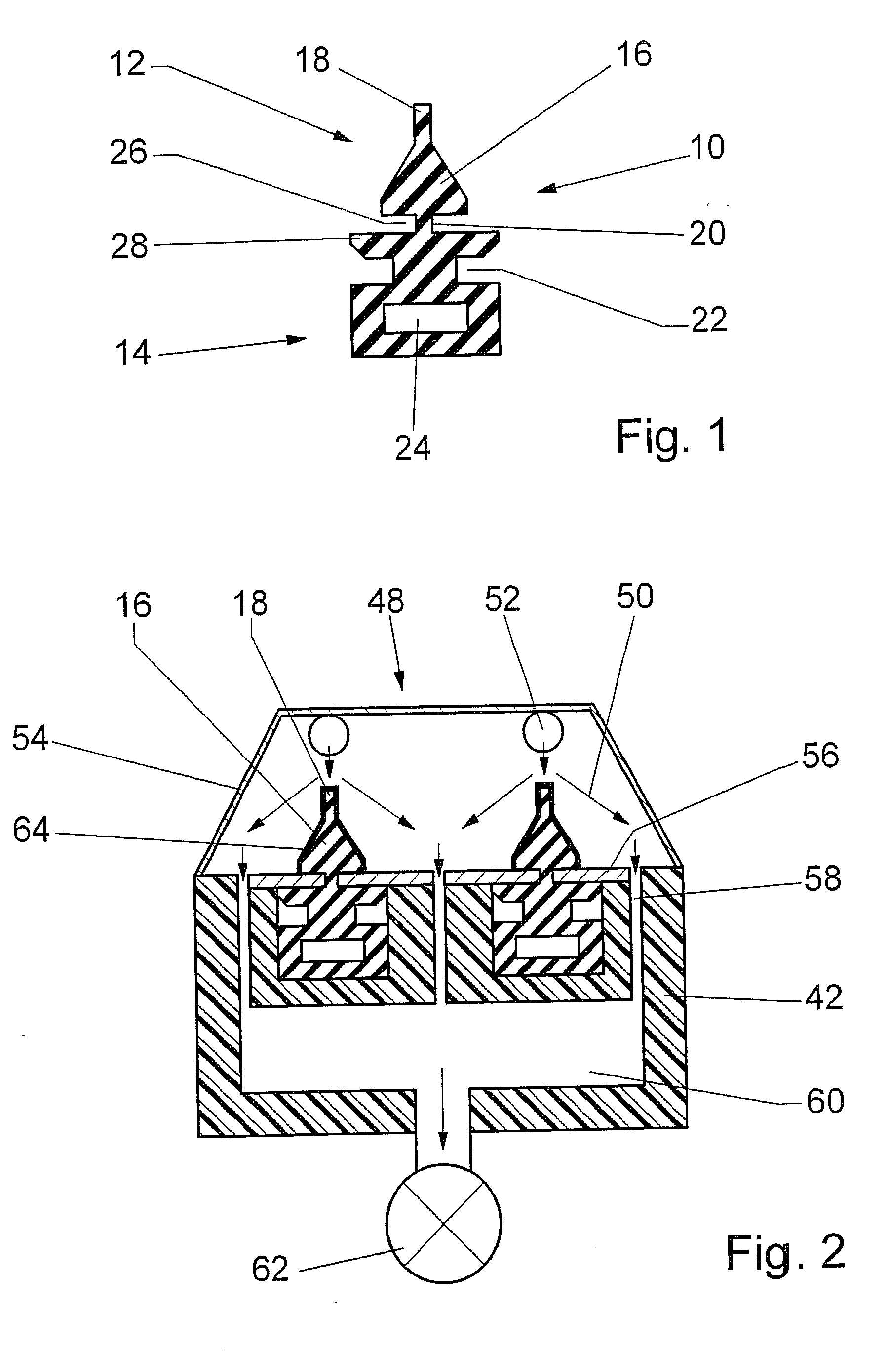
[0023] The wiper blade element 10 according to FIG. 1 has a profiled back 14 and an operational part 12 with a wiper wedge 16 and a wiper lip 18 formed thereon. A tilting piece 20 connects the operational part 12 to the profiled back 14 and permits the wiper lip 18 to tilt over in the reversal positions of the wiper so that the wiper lip 18 encloses an acute angle with the vehicle window in the wiping direction. Along both sides of the tilting piece 20, longitudinal grooves 26 are formed between the wiper wedge 16 and a covering strip 28 of the profiled back 14. In the tilting motion, one shoulder of the wiper wedge 16 rests against the covering strip 28 and this limits the tilting motion. In addition, claw grooves 22 extend on both sides of the profiled back 14 and are engaged by the claws of a claw bracket of the wiper, which are not shown in detail. Finally, the profiled back 14 has a longitudinal channel 24 into which a spring strip, not shown in detail, is inserted in order to ...


PUM

PropertyMeasurementUnit
pressureaaaaaaaaaa
frequencyaaaaaaaaaa
frequencyaaaaaaaaaa

Abstract

The invention is based on a method for coating at least one wiper blade element (10) made of an elastomer material, in which first, the surface of the wiper blade element (10) is cleaned and activated by means of a plasma, and then in a CVD process, a coating material is brought into a plasma state and at least one protective coating (64) forms on the surface of the wiper blade element (10), where a high-frequency voltage is applied to the region of the wiper blade element (10) oriented away from the protective layer (64) by means of an electrode (56). The invention proposes that before being brought into a treatment chamber (32, 34, 36, 38, 40, 74), the wiper blade element (10) be cut to a useful length (66) from a profiled band and placed on an electrode plate (56) so that its wiper lip (18) stands approximately perpendicular to the electrode plate (56), which extends to both sides of the wiper blade element (10), and is subjected to a plasma flow (50). (FIG. 2)

Description

PRIOR ART[0001] The invention is based on a method for coating at least one wiper blade element according to the preamble to claim 1.[0002] Wiper blade elements for vehicle window wipers are produced in mass quantities, typically more than ten thousand per day. They are cut from a rubber strip that has been extruded and then vulcanized.[0003] DE 198 14 805 A1 has disclosed a method for coating a wiper blade element, in which at least one protective coating is produced on the surface of the extruded, elastomer material of the wiper blade element by means of a CVD process (Chemical Vapor Deposition) in order to improve the abrasion and sliding properties of the wiper blade element. So that the protective coating adheres better to the base material, the surface of the wiper blade element is pretreated by being cleaned and activated with a plasma. A layer of bonding agent can also be applied.[0004] It is also known that a bias voltage applied to the wiper blade element causes the plasma...

Claims


Application Information

Patent Timeline
Patent Type & Authority Applications(United States)
IPC IPC(8): B60S1/38C08J7/06C23C16/02C23C16/458C23C16/509
CPCB60S2001/3829C23C16/509C23C16/458C23C16/0245C23C16/44
Inventor BURGER, KURTSCHNEIDER, GUENTERBURGHOFF, KLAUSWEBER, THOMASFORGET-FUNK, JEANNE
Owner ROBERT BOSCH GMBH
Why Eureka
Try Eureka