Process for selectively producing light olefins

a selective production and light olefin technology, applied in the field of selective production of light olefins, can solve the problems of increasing the cost of recovery of desirable light olefins, high operating cost, and large capital investment required by the process, and achieves the effect of reducing the cost of recovery of undesirable light olefins and reducing the cost of recovery

Inactive Publication Date: 2002-11-14
STEFFENS TODD R +1
View PDF50 Cites 4 Cited by
  • Summary
  • Abstract
  • Description
  • Claims
  • Application Information

AI Technical Summary

Problems solved by technology

However, these types of processes typically require relatively large capital investments as well as high operating costs.
One problem inherent in conventional light olefin production using FCC units is that the process depends on a specific catalyst balance to maximize production of light olefins while also achieving high conversion of the 650.degree. F. plus feed components.
In addition, even if a specific catalyst balance can be maintained to maximize overall light olefin production, light olefin selectivity is generally low due to undesirable side reactions, such as extensive cracking, isomerization, aromatization and hydrogen transfer reactions.
Light saturated gases produced from undesirable side reactions result in increased costs to recover the desirable light olefins.
Another problem associated with conventional olefin production via the cracking of higher molecular weight hydrocarbon species using zeolite catalysts is that the catalyst requires steam activation prior to use to provide sufficient conversion activity.
Moreover, some conventional light olefin processes using catalyst steam activation exhibit little if any light olefin selectivity increase in connection with the activity increase.
The catalyst may be activated prior to use in a light olefin conversion reaction, thereby increasing process and equipment requirements.
This method detrimentally reduces initial light olefin yield compared to steady state yield because the initial catalyst charge requires a period of time for activation.
In-situ steam activation also leads to a diminished steady-state yield because fresh catalyst make-up added during the process requires a period of time for activation.
However, such steam does not substantially affect the catalyst's activity for propylene yield.

Method used


Image

  • Process for selectively producing light olefins
  • Process for selectively producing light olefins
  • Process for selectively producing light olefins

Examples


Embodiment Construction

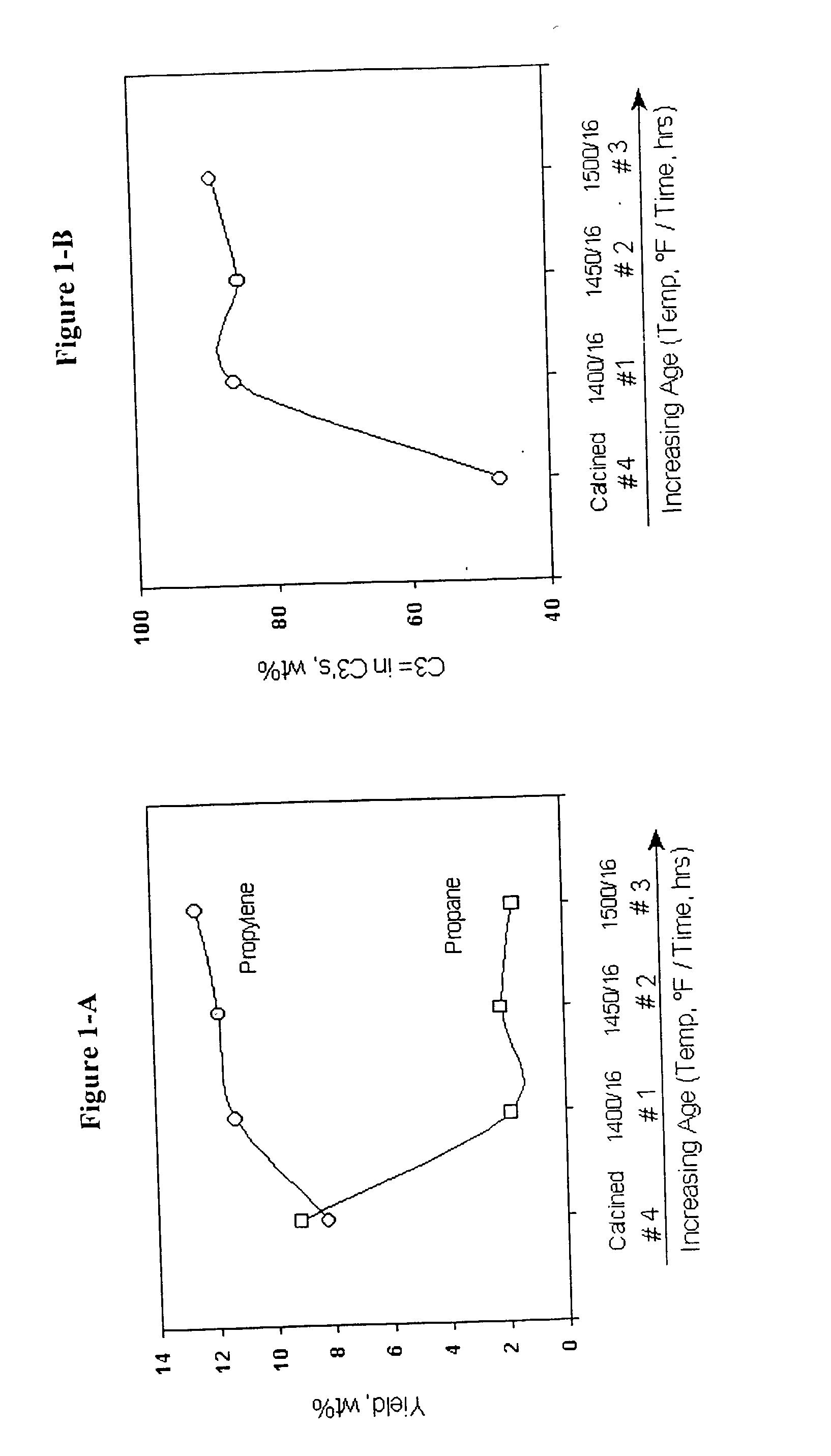
[0063] 1. Three samples of the same conventional naphtha cracking catalysts having 40 wt. % ZSM-5 content were calcined at 1000.degree. F. for four hours and then steam activated at a steam pressure of 1 atmosphere external to the naphtha cracking reactor under conventional conditions at 1400.degree. F. (sample 1), 1450.degree. F. (sample 2), and 1500.degree. F. (sample 3) for 16 hours. For comparison purposes, a fourth sample (sample 4) was not steam treated but calcined at 1000.degree. F. for four hours. The four catalysts were employed under simulated riser reactor conditions to convert a catalytically cracked naphtha boiling in the range of C.sub.5 to 430.degree. F. and having a 22 wt. % olefin content. Conversion conditions included a reactor temperature of about 575.degree. C. and a catalyst to naphtha (wt. / wt.) ratio of about 10. As can be seen in FIG. 1-A, the three samples that were steam pretreated showed an increased activity for propylene production and a decreased activ...


PUM

PropertyMeasurementUnit
pore diameteraaaaaaaaaa
temperatureaaaaaaaaaa
weight ratioaaaaaaaaaa

Abstract

The invention is related to a catalyst and a process for selectively producing light (i.e., C2-C4) olefins from a catalytically cracked or thermally cracked naphtha stream. The naphtha stream is contacted with a catalyst containing from about 10 to 50 wt. % of a crystalline zeolite having an average pore diameter less than about 0.7 nanometers at reaction conditions. The catalysts do not require steam activation.

Description

[0001] This is a continuation-in-part of U.S. Ser. No. 09 / 073,085 filed May 5, 1998.BACKGROUND OF THE DISCLOSURE[0002] 1. Field of the Invention[0003] The present invention relates to a process for catalytically converting a naphtha containing olefin in a process using a shape selective catalyst that does not require steaming to provide activity and selectively. More particularly, the invention relates to the use of such catalysts for producing light (i.e., C.sub.2-C.sub.4) olefins from a naphtha, and preferably from a catalytically cracked or thermally cracked naphtha stream. The naphtha stream is contacted with a catalyst containing from about 10 to 50 wt. % of a crystalline zeolite having an average pore diameter less than about 0.7 nanometers at reaction conditions which include temperatures from about 500.degree. C. to about 650.degree. C. and a hydrocarbon partial pressure from about 10 to 40 psia.[0004] The need for low emissions fuels has created an increased demand for ligh...

Claims


Application Information

Patent Timeline
Patent Type & Authority Applications(United States)
IPC IPC(8): C07B61/00C07C4/06C07C4/04C07C11/02C07C11/04C07C11/06C10G11/02C10G11/04C10G11/05C10G11/18C10G35/02C10G35/04C10G35/06C10G35/095C10G51/02C10G51/04C10G57/02
CPCC10G11/05C10G2400/20C10G57/02C10G51/023
Inventor STEFFENS, TODD R.LADWIG, PAUL K.
Owner STEFFENS TODD R
Why Eureka
Try Eureka