
Apparatus and method for lubricating feed mechanism of forming machine

a technology of forming machine and feed mechanism, which is applied in the direction of manufacturing tools, other domestic articles, and castings. it can solve the problems of uneven lubrication conditions at respective portions of the ball screw, difficult to maintain a uniform lubricant film, and difficult to maintain the lubricant film

Inactive Publication Date: 2002-11-21
SUMITOMO HEAVY IND LTD
View PDF8 Cites 13 Cited by
  • Summary
  • Abstract
  • Description
  • Claims
  • Application Information

AI Technical Summary

Benefits of technology

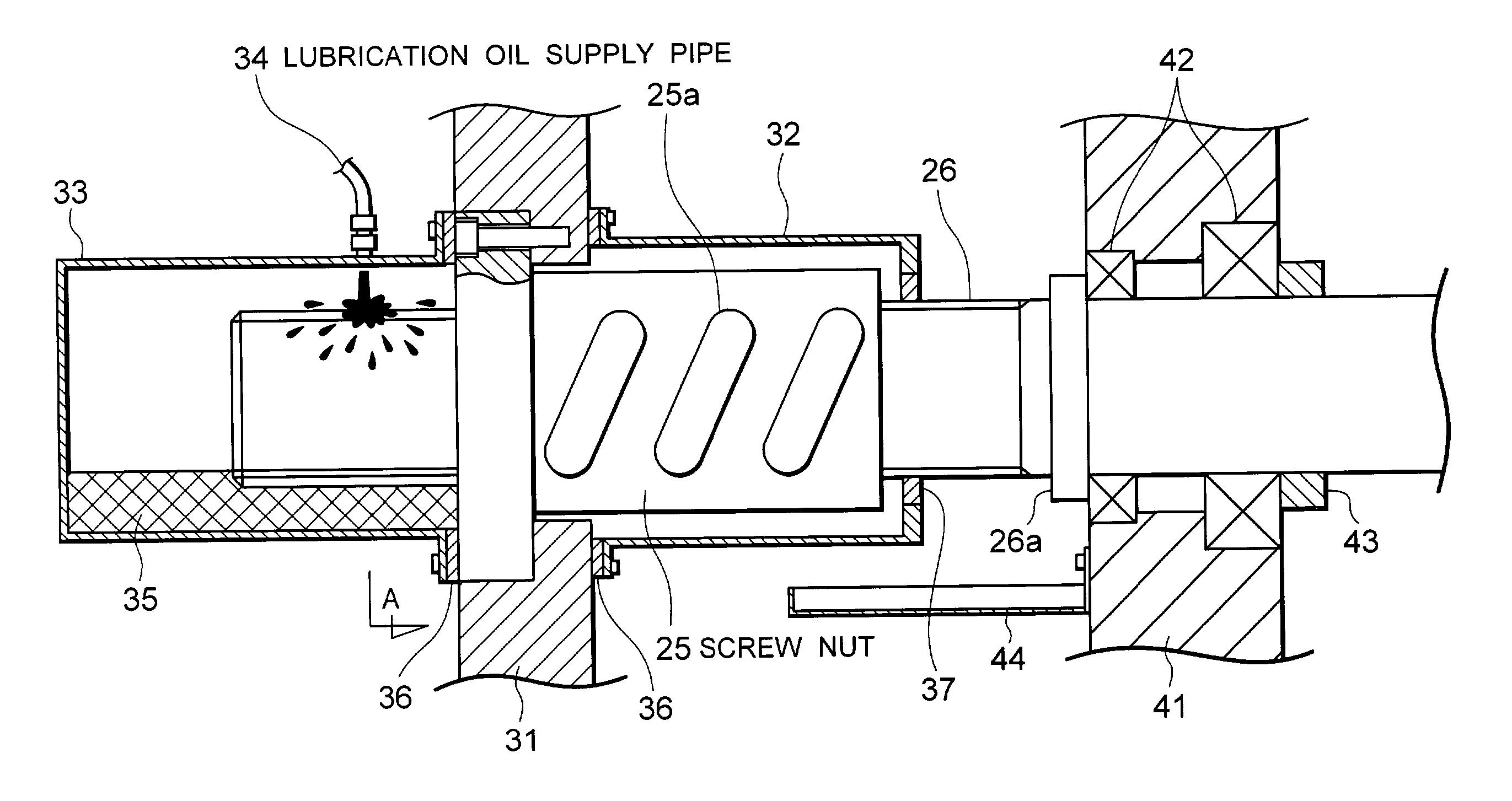
[0018] An object of the present invention is to solve the above-mentioned problems in conventional techniques and to provide an apparatus and method for lubricating a feed mechanism of a forming machine which can maintain uniform film of lubrication oil on contact surfaces of respective portions of the feed mechanism to thereby prolong service lives of the respective portions of the feed mechanism, reduce maintenance cost, prevent contamination of the forming machine and an area surrounding the forming machine, and prevent wear of the contact surfaces.

Problems solved by technology

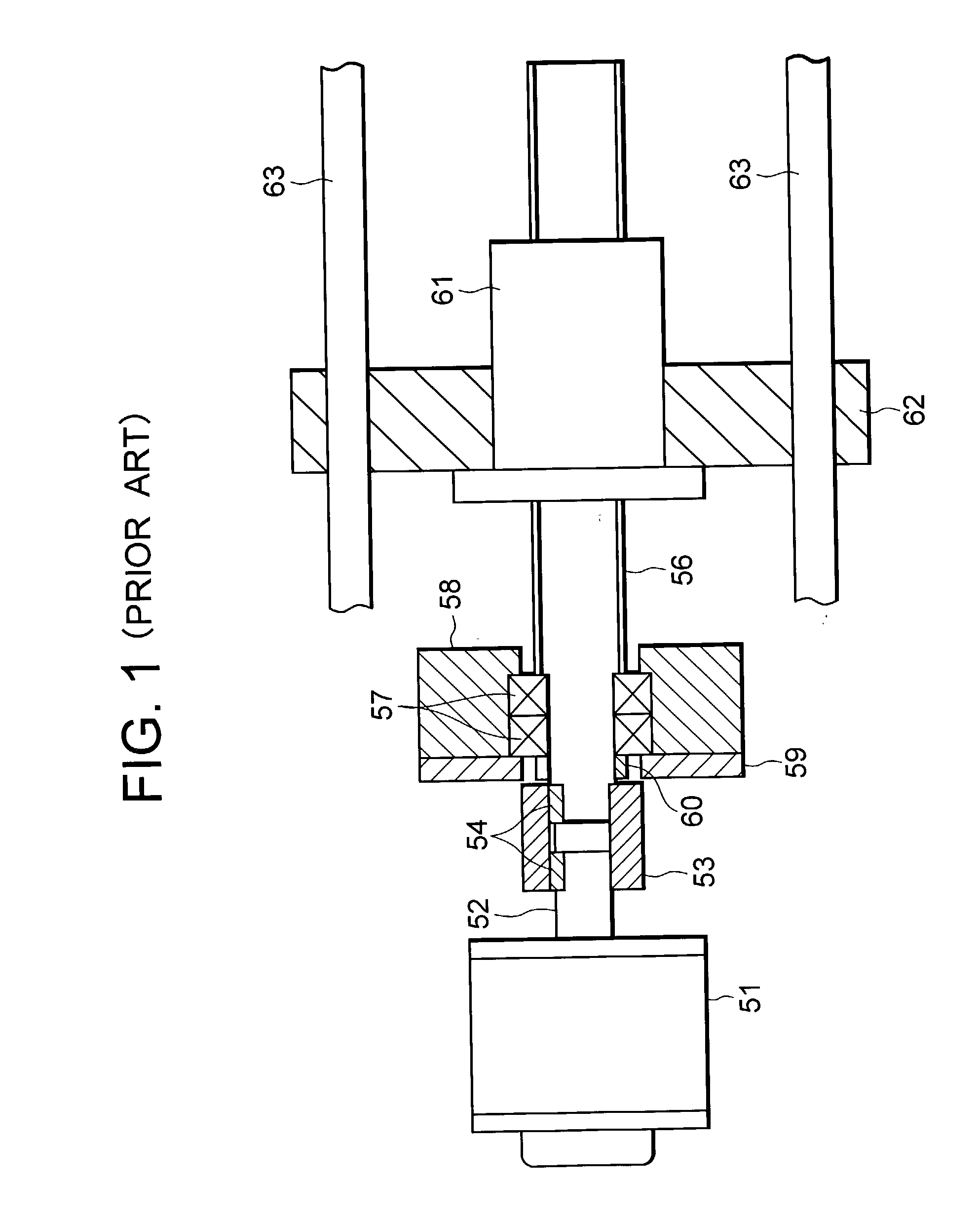
However, in the conventional ball screw serving as a feed mechanism, since grease is used for lubrication, maintaining a uniform film of lubricant at the contact surfaces between the balls and the screw is difficult.
Consequently, lubrication conditions at respective portions of the ball screw become uneven.
In particular, when the stroke of movement of the ball-screw shaft relative to the ball-screw nut is short, the grease is pushed out from the contact surfaces between the balls and the screw, and therefore, maintaining the lubricant film is difficult.
As a result, there arises a variation in service life among the respective portions of the ball screw, thereby shortening the overall service life of the ball screw.
When the supply rate of grease is set greater than a required rate in order to guarantee that grease is distributed sufficiently to respective portions of the ball screw, consumption of grease increases.
In general, grease is expensive, and therefore, the increased consumption of grease renders maintenance cost of the forming machine extremely high.
Further, when the supply rate of grease is increased, excessive grease overflows, scatters, and contaminates the forming machine and an area surrounding the forming machine.
Further, when the ball screw is used for a long period of time, iron particles generated due to wear contaminate grease.
However, when the supply rate of grease is increased in order to discharge grease containing iron particles as soon as possible, grease is discharged from the ball screw at a high rate, resulting in increased maintenance cost and contamination of the forming machine and an area surrounding the forming machine, as described above.
Moreover, since grasping the progress of wear of the ball screw is difficult, the service life of the ball screw cannot be predicted accurately.
As a result, the feed mechanism of the forming machine operates erratically, whereby the accuracy of formed products decreases, and other components of the forming machine are affected adversely.
Meanwhile, when the ball-screw shaft and the ball-screw nut are replaced prematurely in order to avoid use of the ball screw beyond its service life, the maintenance cost of the forming machine increases.
However, this method requires stopping a forming machine so as to collect grease adhering to the ball-screw shaft and the ball-screw nut.
Meanwhile, the frequency of operation of collecting grease is decreased in order to shorten the total stoppage time of the forming machine, prediction accuracy deteriorates.

Method used


Image

  • Apparatus and method for lubricating feed mechanism of forming machine
  • Apparatus and method for lubricating feed mechanism of forming machine
  • Apparatus and method for lubricating feed mechanism of forming machine

Examples


first embodiment

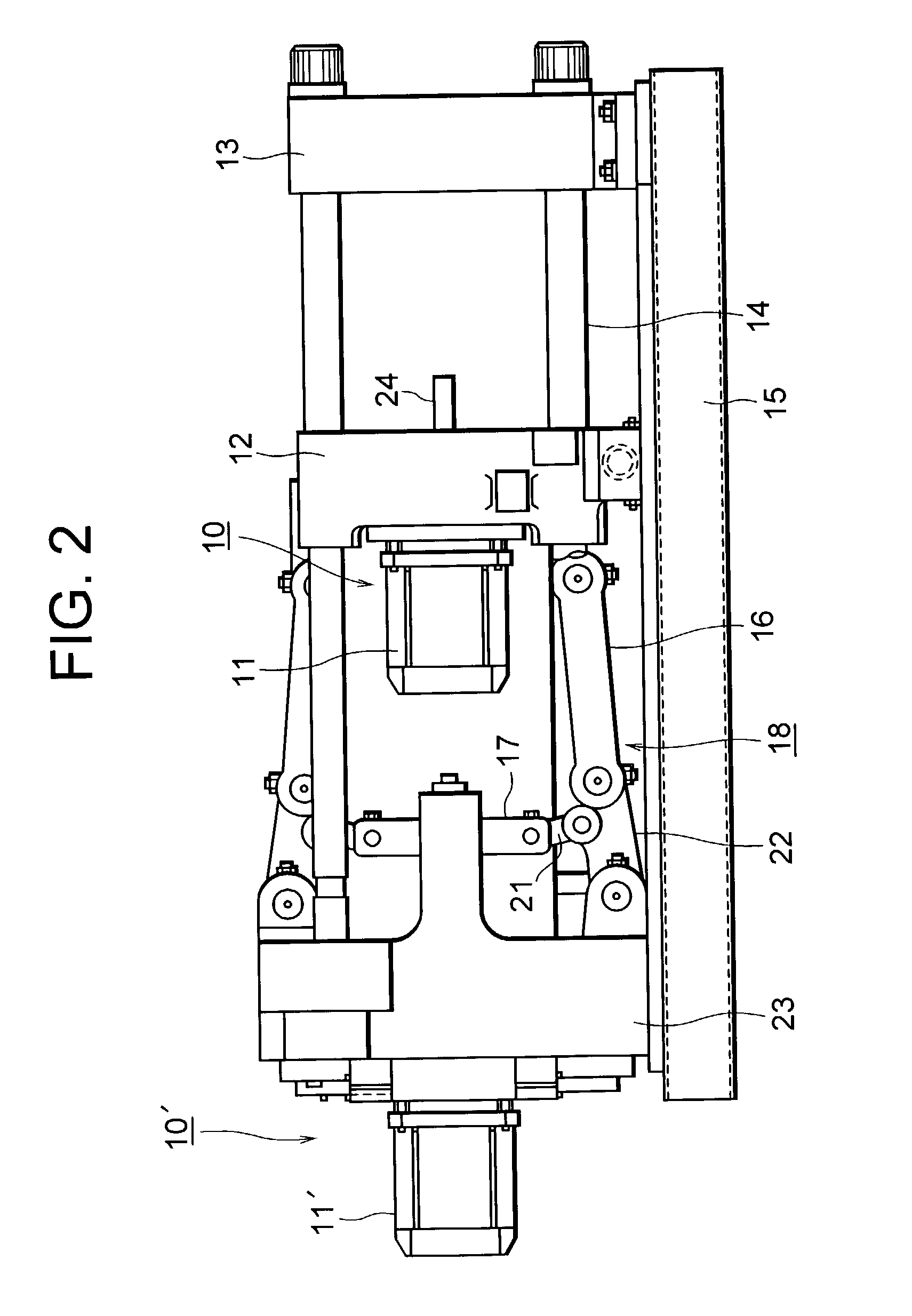
[0075] FIG. 2 is a schematic view of a mold clamping apparatus of an injection molding machine according to the present invention.

[0076] In FIG. 2, reference numeral 15 denotes a frame; 13 denotes a stationary platen, which is fixed to the frame 15; 23 denotes a toggle support, serving as a base plate, which is movably disposed on the frame 15 and is separated a predetermined distance from the stationary platen 13; 14 denotes tie bars which are disposed to extend between the stationary platen 13 and the toggle support 23; and 12 denotes a movable platen which is disposed to face the stationary platen 13 and is reciprocatable (can be moved leftward and rightward in FIG. 2) along the tie bars 14. An unillustrated stationary mold is attached to a surface of the stationary platen 13, which surface faces the movable platen 12. An unillustrated movable mold is attached to a surface of the movable platen 12, which surface faces the stationary platen 13.

[0077] A dive unit 10 is attached to ...

third embodiment

[0131] FIG. 14 is a diagram showing the configuration of the iron-content measurement unit used in the present invention.

[0132] In FIG. 14, reference numeral 74 denotes a first excitation coil, which is disposed in such a manner that the lubrication oil supply pipe 34 passes through the center thereof. Reference numeral 75 denotes a second excitation coil, which is disposed to face the first excitation coil 74. However, the lubrication oil supply pipe 34 does not pass through the center of the second excitation coil 75. A detection coil 77 is disposed at the midpoint between the first excitation coil 74 and the second excitation coil 75. The first excitation coil 74 and the second excitation coil 75 have the same configuration and are excited by the same current output from an oscillation circuit 76. Therefore, the first excitation coil 74 and the second excitation coil 75 generate magnetic fields of the same intensity in the same direction.

[0133] Therefore, at the midpoint between ...


PUM

PropertyMeasurementUnit
poweraaaaaaaaaa
pressureaaaaaaaaaa
rotationaaaaaaaaaa

Abstract

A lubrication apparatus lubricates a feed mechanism of a molding machine. The lubrication apparatus includes a storage member for storing lubrication oil therein, and a lubrication oil circulation pipe connected to the storage member.

Description

[0001] 1. Field of the Invention[0002] The present invention relates to an apparatus and method for lubricating a feed mechanism of a forming machine. Description of the[0003] 2. Related Art[0004] Conventionally, in a forming machine, such as an injection molding machine, resin heated and melted in a heating cylinder is injected into a cavity of a mold apparatus under high pressure so that the cavity is filled with the molten resin. The molten resin is then cooled and solidified within the cavity so as to produce a molded article.[0005] The mold apparatus consists of a stationary mold and a movable mold. A mold clamping apparatus for advancing and retracting the movable mold is provided so as to bring the movable mold into contact with the stationary mold and separate the same from the stationary mold, to thereby effect mold closing, mold clamping, and mold opening.[0006] The mold clamping apparatus has a toggle mechanism for advancing and retracting the movable mold. The toggle mec...

Claims


Application Information

Patent Timeline
Patent Type & Authority Applications(United States)
IPC IPC(8): B29C45/83F16H25/22F16H57/04
CPCB29C45/83B29C2037/92B29C2045/835F16H25/2204Y10T74/18744F16H57/0402F16H57/0434F16H57/0497F16H25/2247
Inventor TAKANOHASHI, RYUICHISUZUKI, MITSUO
Owner SUMITOMO HEAVY IND LTD
Learn More