

Head suspension for disk drive and method of manufacturing head suspension
a technology of disk drives and head suspensions, applied in the direction of supporting heads, instruments, record information storage, etc., can solve the problems of increasing costs, bending such a multi-layer structure difficult to correctly achieve, and the head is moved away from the track center
- Summary
- Abstract
- Description
- Claims
- Application Information
AI Technical Summary
Benefits of technology
Problems solved by technology
Method used
Image

Examples
first embodiment
[0077] FIG. 4 is a sectional view partly showing a hard disk drive incorporating head suspensions according to the first embodiment of the present invention. The hard disk drive 1 has a carriage 5. The carriage 5 is driven by a positioning motor 7 such as a voice coil motor and turns around a spindle 3. The carriage 5 has a plurality of (four in FIG. 1) carriage arms 9 each supporting the head suspension 11 at a front end thereof. The head suspension 11 has a head 13 at a front end thereof.
[0078] The carriage 5 is turned around the spindle 3, to move the heads 13 onto target tracks on disks 15. Each head 13 has a slider 17 facing tracks on the disk 15. The slider holds a transducer (not shown).
[0079] When the disks 15 are rotated at high speed, air enters between the disks 15 and the sliders 17, so that the sliders 17 slightly float from the disks 15 and air bearings are formed between the disks 15 and the sliders 17.
[0080] FIG. 5 is a perspective view showing one of the head suspen...
second embodiment
[0158] FIG. 21 is a plan view showing a head suspension 11A for a disk drive according to the second embodiment of the present invention, and FIG. 22 is a sectional view showing head suspensions 11A attached to carriage arms 9. Parts corresponding to those of the first embodiment are represented with like reference numerals.
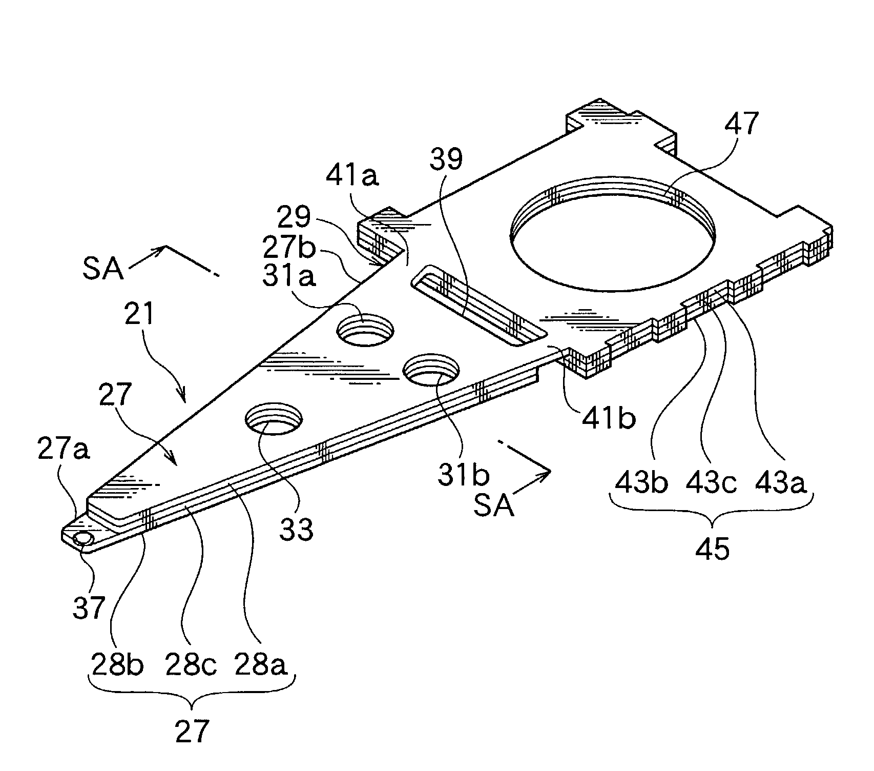
[0159] The head suspension 11A is appropriate when the distance between a fitting point on the carriage arm 9 and a dimple 37 is long. A rigid part 27 of the head suspension 11A has a three-layer structure including metal layers 28a and 28b and a resin layer 28c interposed between the metal layers 28a and 28b. A resilient part 29A of the head suspension 11A is integral with the metal layer 28b and is formed at an end of the rigid part 27. Opposite the rigid part 27, the resilient part 29A has an integral support 103.
[0160] A base 19A of the head suspension 11A has a base plate 22. A flange 23 of the base plate 22 is provided with an extension 105. The extension 1...
third embodiment
[0163] FIG. 23 is a sectional view showing a head suspension 11B for a disk drive according to the third embodiment of the present invention. Parts corresponding to those of the first embodiment are represented with like reference numerals.
[0164] A reinforcing part 45B of the head suspension 11B has lightening holes (not shown). A base 19B of the head suspension 11B has a boss 25 having a hole (not shown).
[0165] The head suspension 11B has a load beam 21B including a rigid part 27B and a resilient part 29B. According to the third embodiment, the rigid part 27B has a three-layer structure including metal layers 107a and 107b and a resin layer 107c interposed between the metal layers 107a and 107b, plus resin layers 107e and 107g formed on top and bottom faces of the three-layer structure, respectively, and metal layers 107d and 107f formed on the resin layers 107e and 107g, respectively. Namely, the rigid part 27B has a seven-layer structure.
[0166] Like the rigid part 27B, the reinfo...
PUM
| Property | Measurement | Unit |
|---|---|---|
| thicknesses t1 | aaaaa | aaaaa |
| weight | aaaaa | aaaaa |
| total weight | aaaaa | aaaaa |
Abstract
Description
Claims
Application Information