
Pop-up electronic equipment enclosure

Inactive Publication Date: 2002-12-12
LINDAMOOD KIRK
View PDF0 Cites 24 Cited by
  • Summary
  • Abstract
  • Description
  • Claims
  • Application Information

AI Technical Summary

Benefits of technology

[0014] A second object of the invention is to protect electronic equipment from weather or hazards of a harsh environment. The pop-up equipment enclosure solves this problem by totally surrounding the equipment with sheeting. The sheeting is chosen with properties to prevent the anticipated environmental hazard from penetrating into the enclosure. The equipment is thus in a hazard-free environment.
[0016] A fourth object of the invention is to take minimal storage space when not in use, The pop-up equipment enclosure provides this by its ability to collapse almost flat. Storage of the collapsed enclosure takes minimal space. Straps with fasteners of velcro patches or mechanical fasteners secure the bottom of the unit in the folded position, and velcro patches secure the sides of the unit in the folded position, thus preventing the collapsed enclosure from opening when stored flat and empty, or when collapsed around an enclosed electronic device.
[0018] A sixth object of the invention is to restrict access to the electronic equipment display by a casual observer, The pop-up equipment enclosure provides this by being constructed of opaque sheeting with a viewing window that can be shielded by the user's body to preclude casual observers from observing the display. In addition, the glare guard inside the unit further restricts unwanted viewing by blocking the lower part of the equipment display from all but the user's eyes.BRIEF DESCRIPTION OF THE SEVERAL VIEWS OF THE DRAWINGS

Problems solved by technology

Using such equipment in public places indoors and outdoors and on transportation vehicles such as airplanes, trains, buses, vans, presents a number of issues.
These issues involve convenience of equipment transport; privacy of the information displayed on the portable equipment; equipment security if left unattended; equipment protection from hazards such as direct sunlight, wind-blown debris, air-born dust, and moisture; and visibility of the equipment display in sunlight or in very brightly lit indoor areas.
Using portable electronic equipment in industrial environments can also present equipment protection issues.
Once the equipment is in use the sensitive portions of the equipment are open to the environment and subject to dust, dirt, and moisture intrusion; observation by the casual passerby; and poor visibility of the display in sunlight or brightly lit indoor areas.
Another example is U.S. Pat. No. 5,400,903 (Cooley), which primarily addresses equipment protection and privacy, although it additionally addresses the use of glare reducing coatings to assist in display visibility in sunlight, a less effective solution than simply providing shade for the display.
These cases have the undesirable property of requiring the user to carry the substantial additional weight of the case when transporting the equipment.
These cases also present their own storage problem when it is desired to use the electronic equipment without the case, such as when the user is home or in the office.
Since the case is rigid and of substantial size, it presents a storage problem, taking up valuable space.
These cases also are limited to use with a laptop computer or similarly configured electronic equipment.
They could not easily be used with other electronic equipment, such as portable industrial measurement and test equipment, or a portable television.
Such hoods do not provide total enclosure of the equipment and thus provide little equipment environmental hazard protection or security when the equipment is unattended.
A computer display can be difficult to see in a brightly lit environment as the bright light overwhelms the luminescence of the display.
The pop-up equipment enclosure is lightweight due to its construction.
In addition, the glare guard inside the unit further restricts unwanted viewing by blocking the lower part of the equipment display from all but the user's eyes.

Method used


Image

  • Pop-up electronic equipment enclosure
  • Pop-up electronic equipment enclosure
  • Pop-up electronic equipment enclosure

Examples


Embodiment Construction

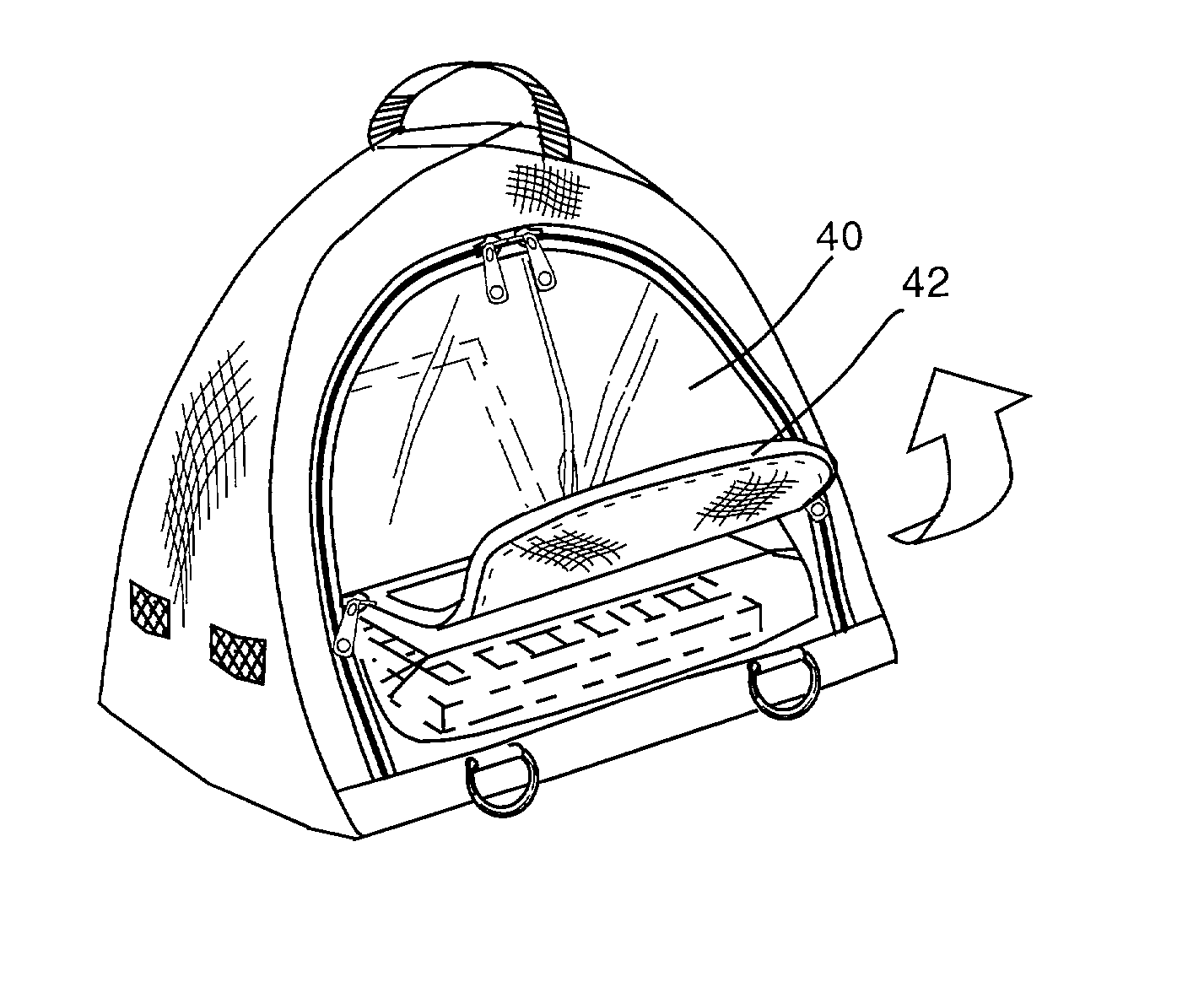
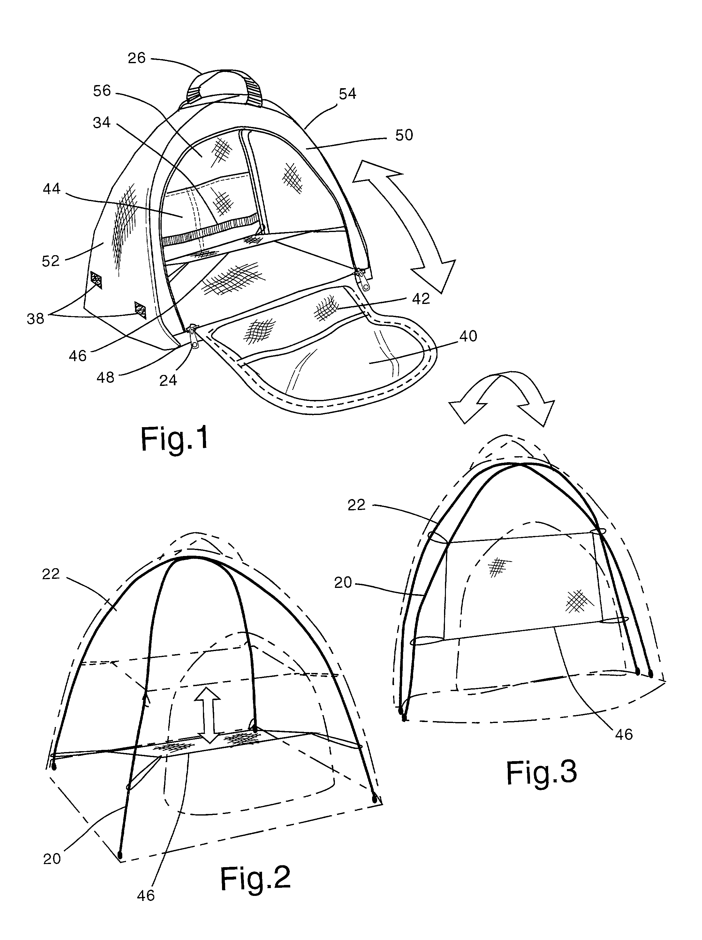
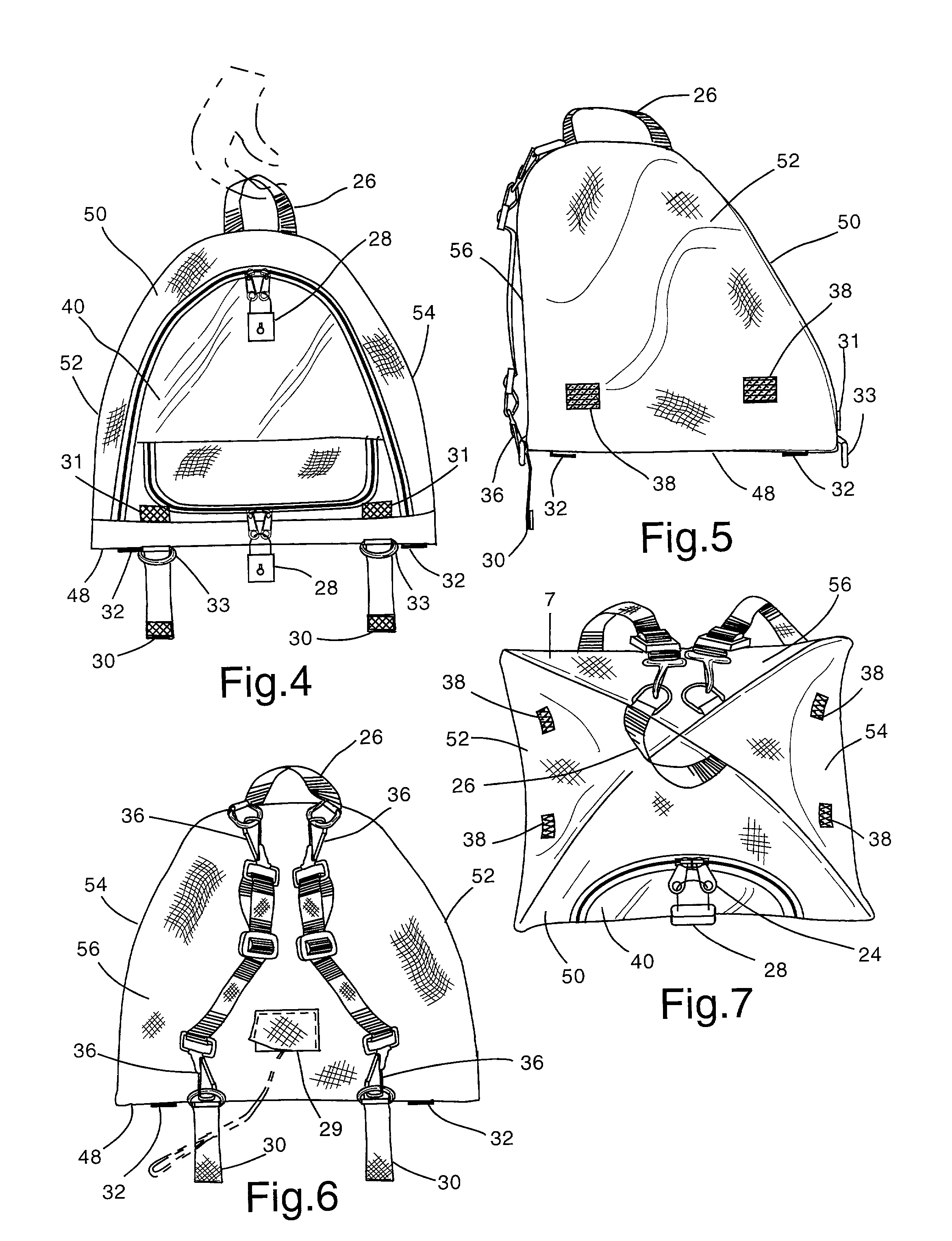
[0054] FIG. 1 shows the preferred embodiment of the pop-up equipment enclosure. In the preferred embodiment, the enclosure is equipped to contain and operate a portable (laptop) computer. The sheeting shown is an opaque lightweight or waterproof fabric. Portions of the sheeting (example the back piece and front piece) may be multi-layered to contain protective padding between the layers. The sheeting is composed of a rectangular bottom portion (48), and an upper portion substantially in a conic section dome shape. The upper dome portion consists of two side pieces (52) (54), a front piece (50) and a back piece (56). Some pieces of the upper portion and the bottom portion sheeting may be cut from a single piece of sheeting as desired to reduce the number of joints. Sheeting portions and pieces are attached by sewing the joints. Alternately an adhesive joining method, or a combination of methods as will provide a flexible and durable joint may be used. The exterior color of the sheeti...


PUM


Abstract

A collapsible electronic equipment enclosure surrounds portable or tabletop electronic equipment, such as laptop computers, with opaque protective sheeting supported by flexible struts. An opening is provided that may include a transparent window and provision for hand entry to permit use of the contained equipment while it is protected from environmental hazards. Provision is made for equipment display visibility in bright sunshine and lighting. Restricting visibility of the equipment display enhances privacy. The enclosure collapses to store in a narrow space, is lightweight, and can be used to transport the contained equipment either by a carry handle or as a backpack. The enclosure can be anchored to a tabletop for motion protection. It can also be locked closed and the contained equipment fastened by a security cable and lock to provide theft and tamper protection for the contained equipment and the enclosure when unattended.

Description

[0001] Not applicable.STATEMENT REGARDING FEDERALLY SPONSORED RESEARCH AND DEVELOPMENT[0002] Not Applicable.REFERENCE TO A MICROFICHE APPENDIX[0003] Not Applicable.[0004] 1. Field of the Invention[0005] This invention relates to a collapsible, lightweight, portable electronic equipment enclosure or container, specifically to an enclosure for table-top or in-lap use capable of providing ease of access to the equipment, equipment protection, display visibility and privacy while the equipment is in use, security when the user is away from the equipment, and equipment portability and protection when transporting the equipment.[0006] 2. Description of Related Art[0007] Portable electronic equipment, especially the portable computer, is widely used in many environments in addition to the home or office. Using such equipment in public places indoors and outdoors and on transportation vehicles such as airplanes, trains, buses, vans, presents a number of issues. These issues involve convenie...

Claims


Application Information

Patent Timeline
IPC IPC(8): A45C3/00A45C7/00A45C9/00A45C13/02A45F3/04A45F4/04G06F1/16
CPCA45C3/00A45C7/0077A45C9/00A45C13/02A45C2013/025Y10S383/907A45F4/04A45F2003/003A45F2200/0525G06F1/1628A45F3/04
Inventor LINDAMOOD, KIRK
Owner LINDAMOOD KIRK
Learn More