Ir-emitter heating device and method for demolding lenses

a technology of demolding device and iremitter, which is applied in the direction of dough shaping, manufacturing tools, instruments, etc., can solve the problems of fracturing a mold portion, reducing the yield rate of the process, and increasing the possibility of lens damage,

Inactive Publication Date: 2002-12-12
JOHNSON & JOHNSON VISION CARE INC
View PDF63 Cites 16 Cited by
  • Summary
  • Abstract
  • Description
  • Claims
  • Application Information

AI Technical Summary

Benefits of technology

[0021] It is another object of the present invention to provide a silicon carbide (SiC) IR-emitter heating device for demolding ophthalmic lenses that can easily and consistently separate the contact lens mold portions having a contact lens formed therebetween without damaging the lens.
[0022] Another object of the instant invention is to reduce contact lens manufacture process time by separating the greatest number of back curves from front curves in a rapid manufacturing line thereby permitting the fast and efficient production of hydrophilic contact lenses.

Problems solved by technology

With respect to prior art systems for removing the back curve mold halves, inefficient means and damaging forces associated therewith have rendered such devices less desirable for producing high quality lenses, inasmuch as the steps of heating and separation that break the polymerized lens / polymer mold adhesion and provide access to the nearly formed lens occasionally damage the lens, and thereby decreasing the yield rate of the process.
Conversely, the lower the thermal gradients created between the mold halves and the lens, the greater will be the required force to separate the mold portions.
The greater the forces which may be required in separating the mold from the lens, the greater becomes the possibility of fracturing a mold portion and / or damaging the lens.
Furthermore, it is to be understood that a process in which a thermal gradient must be applied on a repeated basis must be such whereby the environment does not heat appreciably, therein reducing the effectiveness of the process.
When front and back curve mold parts, which are designed to form an integral frame such as are illustrated in U.S. Pat. No. 4,640,489, are placed together to form a lens shaped volume therebetween, the resultant combined structure provides limited accessible space for a separating means to engage and displace one mold from the other.
Even minimal warpage of either mold half can adversely affect both accessibility to the space as well as the accuracy of the displacing forces.
This necessitates a longer period of heating and consequently lengthier demold times are required for demolding the lenses.
In general, the process of providing the necessary thermal gradient, as indicated with the use of quartz or sapphire windows on the infra-red heater, filters out a portion of the infra-red radiation, and requires lengthier demolding times. In effect, the quartz glass surrounding the infra-red heating element is subject to breakage and causes an efficacy problem.
However, the combination of the quartz element tube employed in the prior art and the sapphire protective window effectively attenuates the infra-red energy associated with these materials, thereby reducing the available output of the heat source and limiting the use of longer wavelength infra-red energy to excite the lens molds in order to derive the desired temperature gradients.

Method used


Image

  • Ir-emitter heating device and method for demolding lenses
  • Ir-emitter heating device and method for demolding lenses
  • Ir-emitter heating device and method for demolding lenses

Examples


Embodiment Construction

[0047] The ophthalmic lens to be demolded in the practice of the present invention is preferably formed in a volume defined between front and back contact lens mold portions, each of which are formed by the processes set forth in U.S. Pat. No. 5,540,410, assigned to the assignee of the present invention, and the disclosure of which is incorporated by reference herein.

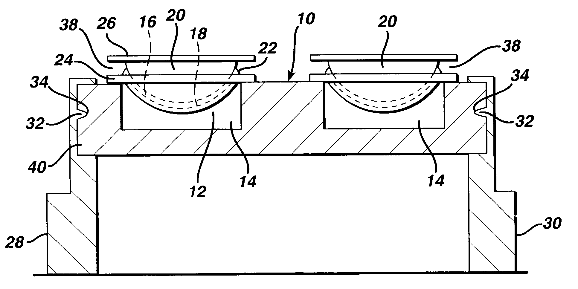
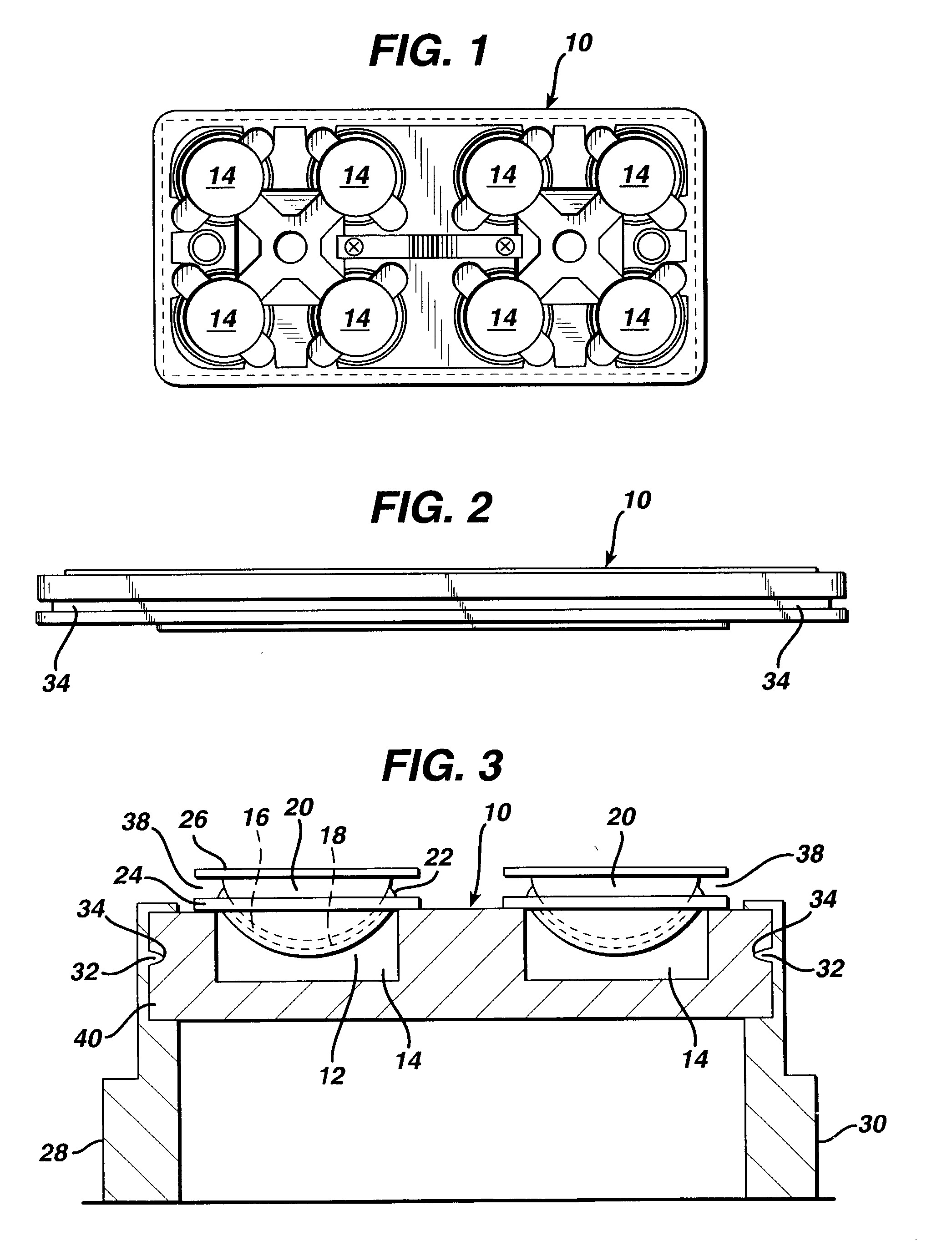
[0048] More particularly, the front and back curve mold portions are preferably transported through the manufacturing line on pallets 10, one of which is shown in FIGS. 1 and 2. Referring also to FIG. 3, it is understood that the front curve portion 12 of the mold is carried within one of the plurality of recesses 14 defined by the pallet 10. In the presently illustrated embodiment of the pallet 10, the pallet 10 has the capacity to carry up to eight front curve molds in its recesses 14. During the process by which the lens is formed, the concave portion 16 of the front curve mold 12 is partially filled with a reactive ...


PUM

PropertyMeasurementUnit
temperatureaaaaaaaaaa
surface roughnessaaaaaaaaaa

Abstract

A method and a device for removing molded soft contact lenses, high-precision intraocular lenses and the like, from the individual molds in which they are produced. Provided is an infra-red radiation or heater device preferably constituted of silicon carbide IR-emitters, and which employs an individual infra-red emitter for each individual mold, to impart a desired thermal gradient. Also provided are infra-red emitters having improved reflectors.

Description

[0001] This is a continuation-in-part application of U.S. Ser. No. 09 / 827,995 filed Apr. 6, 2001 titled Silicon Carbide IR-Emitter Heating Device and Method for Demolding Lenses, which is entirely incorporated herein by reference.[0002] 1. Field of the invention[0003] The present invention relates generally to the production of ophthalmic lenses, and, in particular pertains to a method and a device for removing molded soft contact lenses, high-precision intraocular lenses and the like, from the individual molds in which they are produced.[0004] 2. Discussion of the Prior Art[0005] In view of the intense growth of the ophthalmic contact lens industry, it has become desirable and even necessary to be able to supply contact lenses which are periodically and frequently replaced in order to minimize the possibility of user induced contamination. This has created an opportunity for manufacturers to strive for automated methods and apparatuses that are able to automatically produce high qu...

Claims


Application Information

Patent Timeline
Patent Type & Authority Applications(United States)
IPC IPC(8): G02C7/04B29C33/06B29C33/44B29C35/08B29C37/00B29C39/36B29D11/00B29L11/00
CPCB29C37/0003B29C43/021B29C43/50B29C2035/0822Y10S425/808B29D11/00221B29K2105/0002B29L2011/0016B29L2011/0041B29D11/00211G02C7/04
Inventor PEGRAM, STEPHEN C.KIMBLE, ALLAN W.VOSS, LESLIE A.BINGAMAN, THOMAS P.RICARD, JOSEPH W.KERNICK, EDWARD R.HOOD, CHARLES R.DARABI, H. ANTHONY
Owner JOHNSON & JOHNSON VISION CARE INC
Why Eureka
Try Eureka