Filter apparatus for HVAC system
- Summary
- Abstract
- Description
- Claims
- Application Information
AI Technical Summary
Benefits of technology
Problems solved by technology
Method used
Image
Examples
Embodiment Construction
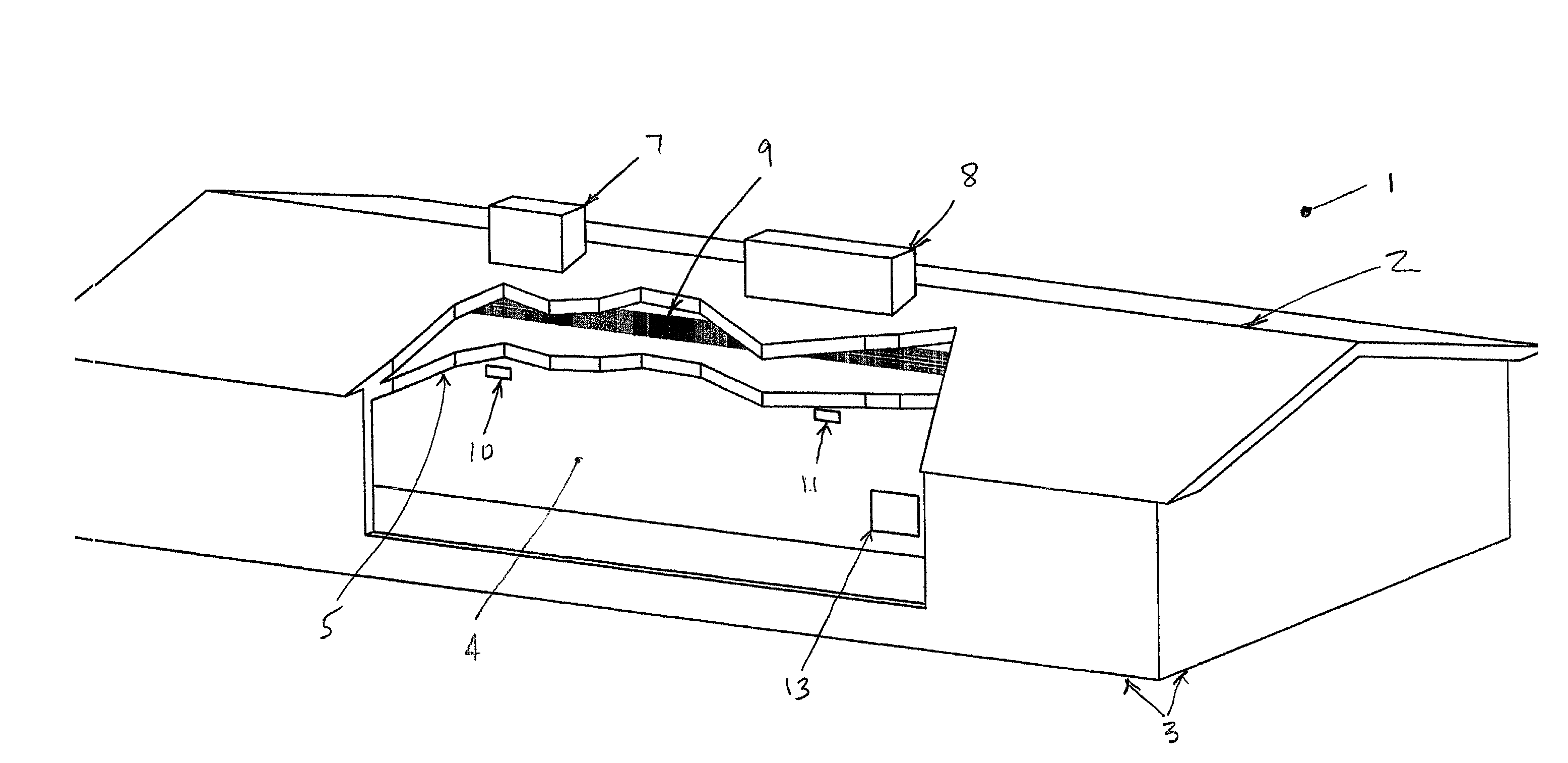
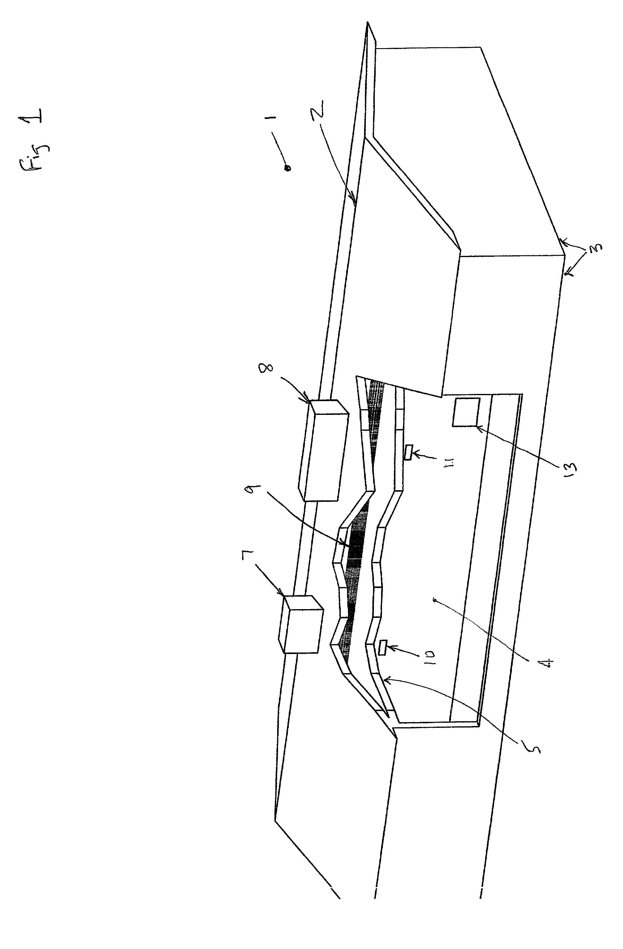
[0039] The filter apparatus of the present invention is advantageously described with reference to the Figures described hereinabove. The present invention is conveniently described in the context of one application therefor, namely, as part of an HVAC system employed in a residential structure in a hot, dry climate. Such a structure is shown schematically at 1 in FIG. 1. The principal elements of the structure are its roof 2, exterior walls 3, interior walls 4 and ceilings 5. FIG. 1 is not intended as a complete drawing of a house and the HVAC system employed therein, but rather as an illustration of principal features thereof. The principal elements of the HVAC system are an evaporative cooler 7, a combination heater-cooler 8, a main distribution duct 9, supply registers 10 and 11, and a return register 13. Note that the evaporative cooler 7 and the heater-cooler 8 are commonly situated on the roof of the structure. Each is connected to the main distribution duct 9 via a connectin...
PUM
| Property | Measurement | Unit |
|---|---|---|
| Pressure drop | aaaaa | aaaaa |
| Area | aaaaa | aaaaa |
| Efficiency | aaaaa | aaaaa |
Abstract
Description
Claims
Application Information
 - R&D
- Intellectual Property
- Life Sciences
- Materials
- Tech Scout
- Unparalleled Data Quality
- Higher Quality Content
- 60% Fewer Hallucinations
Browse by: Latest US Patents, China's latest patents, Technical Efficacy Thesaurus, Application Domain, Technology Topic, Popular Technical Reports.
© 2025 PatSnap. All rights reserved.Legal|Privacy policy|Modern Slavery Act Transparency Statement|Sitemap|About US| Contact US: help@patsnap.com


