Thin walled compartmented tubular structure and its manufacturing process

a tubular structure and manufacturing process technology, applied in the direction of rigid pipes, heat exhanger conduits, pipe elements, etc., can solve the problems of increasing weight, permanent distortion or cracking of leading edge de-icing pipes, and increasing weigh

Inactive Publication Date: 2002-12-26
SONACA
View PDF17 Cites 16 Cited by
  • Summary
  • Abstract
  • Description
  • Claims
  • Application Information

AI Technical Summary

Problems solved by technology

However, permanent distortion or cracking may occur in the leading edge de-icing pipes.
In particular, this distortion occurs at the joints between the various sections of these pipes.
However, this leads to an increase in weight, which is contrary to the objective for aircraft applications.
Tests have shown that the deterioration of the de-icing pipes is essentially due to the vibrations generated by the hot air flowing through them.
This swirling flow generates alternating stresses at the de-icing pipe wall, which may lead to fatigue cracks which are extremely detrimental to safety and to the service life of the constituent parts of the de-icing circuit.
The use of such plates does however present a disadvantage from the point of view of manufacture.
Rework is often required to return

Method used


Image

  • Thin walled compartmented tubular structure and its manufacturing process
  • Thin walled compartmented tubular structure and its manufacturing process
  • Thin walled compartmented tubular structure and its manufacturing process

Examples


Embodiment Construction

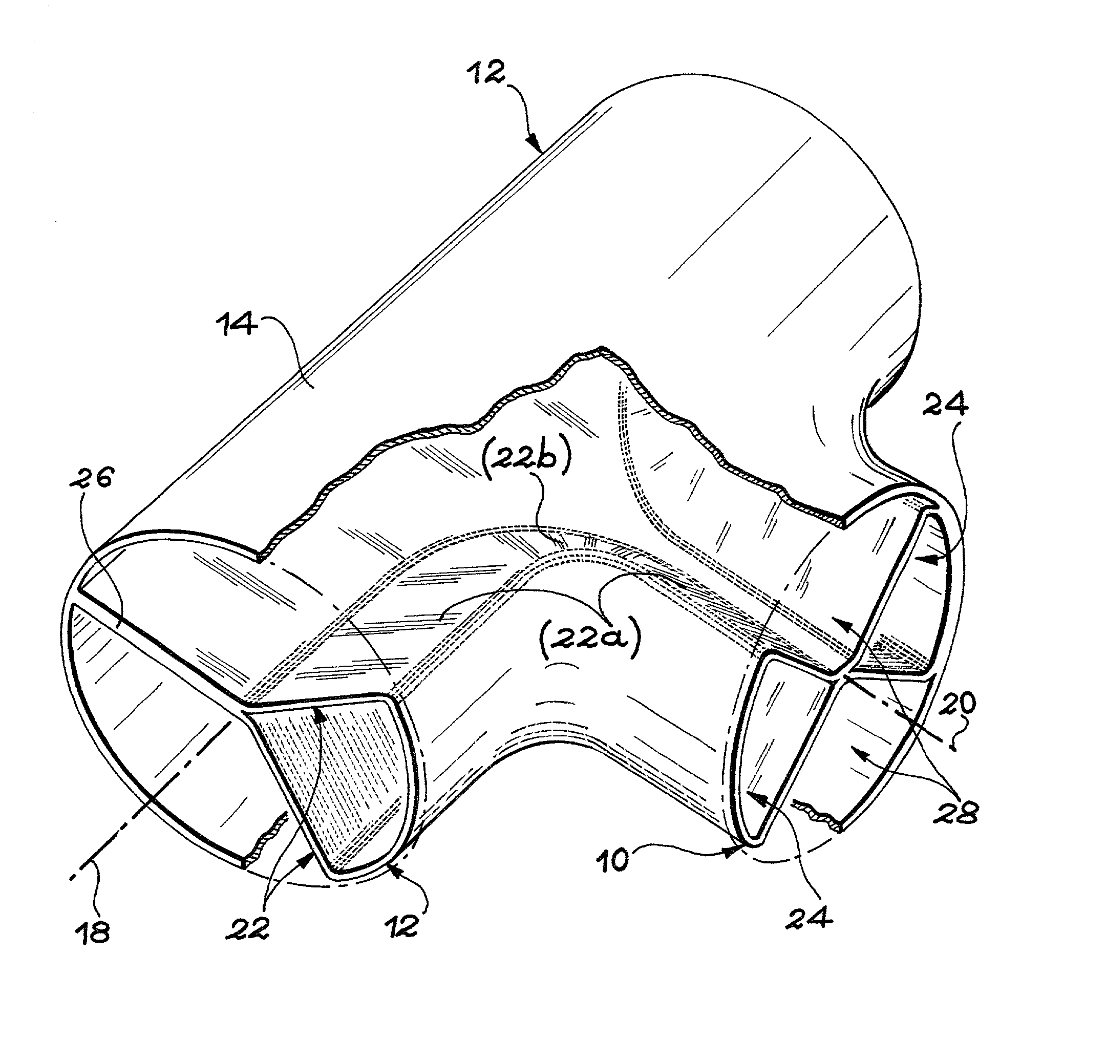
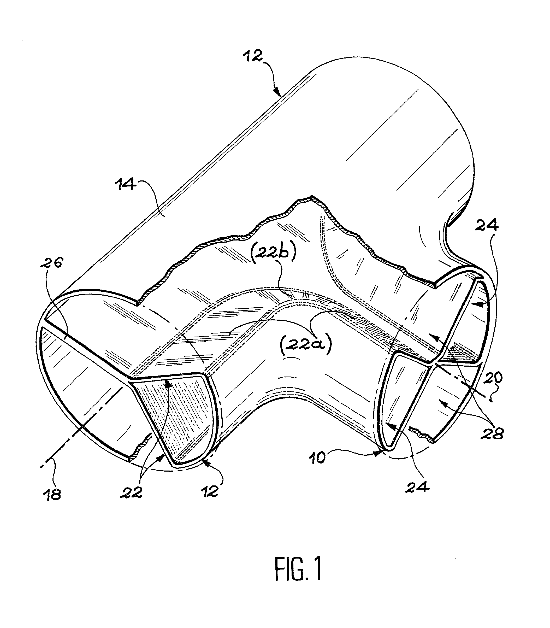
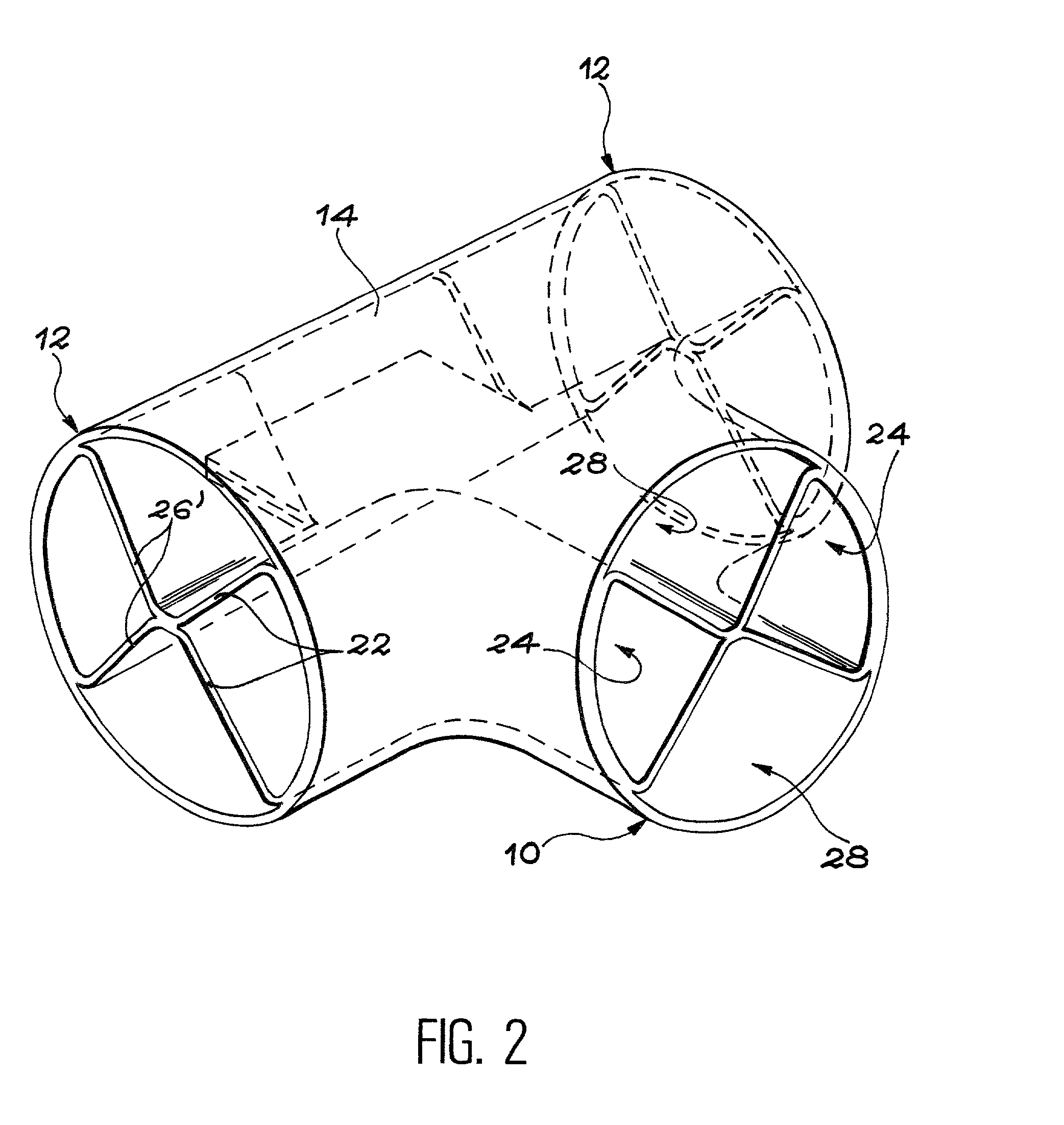
[0035] In the production method illustrated by the figures, the thin walled compartmented tubular structure in accordance with the invention is a T-shaped structure which includes an external wall 14. The external wall 14 of the thin walled compartmented tubular structure in accordance with the invention is formed from a thin gauge sheet, preferably of titanium alloy.

[0036] The thin walled compartmented tubular structure includes an inlet tubular part 10 and two outlet tubular parts 12. More precisely, in the inlet 10 and outlet 12 tubular parts, the external wall 14 exhibits a circular section of approximately the same diameter. Moreover, the outlet tubular parts 12 are centred on a common axis 18, oriented in a direction approximately normal to the axis 20 of the inlet tubular part 10.

[0037] It is important to note that these characteristics should not be considered as limiting the scope of the invention. In particular, the latter covers also an elbow-shaped thin walled compartmen...


PUM

PropertyMeasurementUnit
Thicknessaaaaaaaaaa
Thicknessaaaaaaaaaa
Angleaaaaaaaaaa

Abstract

Thin walled compartmented tubular structure and its manufacturing process. The elbow or T-shaped structure, includes an external wall (14)and continuous internal walls (22) made in one piece. This therefore materialises, between the inlet (10) and each outlet (12) of the structure, at least one continuous passage to direct a fluid circulating inside it. The structure according to the invention is manufactured by diffusion welding and superplastic forming, from titanium alloy sheets. One application is for aircraft de-icing circuits.

Description

DESCRIPTION[0001] 1. Technical Background[0002] The invention concerns a thin walled compartmented tubular structure intended to enable a fluid to flow between an inlet tubular part and at least one outlet tubular part, oriented in different directions, generally although not necessarily mutually perpendicular.[0003] In the expression "thin walled compartmented tubular structure", the term "thin" signifies that the structure is formed exclusively of sheet material less than 2 mm thick.[0004] The invention also concerns a manufacturing process for such a thin walled compartmented tubular structure.[0005] The invention has a useful application in the aircraft industry, and in particular for the manufacture of hot air de-icing devices for the external surfaces of aircraft, such as leading edge flaps on aircraft wings. It may however be used in any other technical application requiring a change of direction of a fluid flowing within a pipe.[0006] 2. State of the Art[0007] On aircraft, h...

Claims


Application Information

Patent Timeline
IPC IPC(8): B21C37/14B21C37/15B21C37/29B21D26/055B64D15/04
CPCB21C37/14B21C37/151B21C37/296Y10S138/11B64D15/04F16L41/021B21D26/055
Inventor DEBAISIEUX, STEPHANEGUEUNING, DIMITRIQUETS, SEBASTIEN
Owner SONACA
Why Eureka
Try Eureka