

Electric hand tool with function-enhancing accessories
a technology of hand tools and accessories, applied in the direction of manufacturing tools, portable drilling machines, flat surface machines, etc., can solve the problems of increasing the cost of hand tools, hardly being able to achieve them, and expanding the potential of use of hand tools
- Summary
- Abstract
- Description
- Claims
- Application Information
AI Technical Summary
Benefits of technology
Problems solved by technology
Method used
Image

Examples
Embodiment Construction
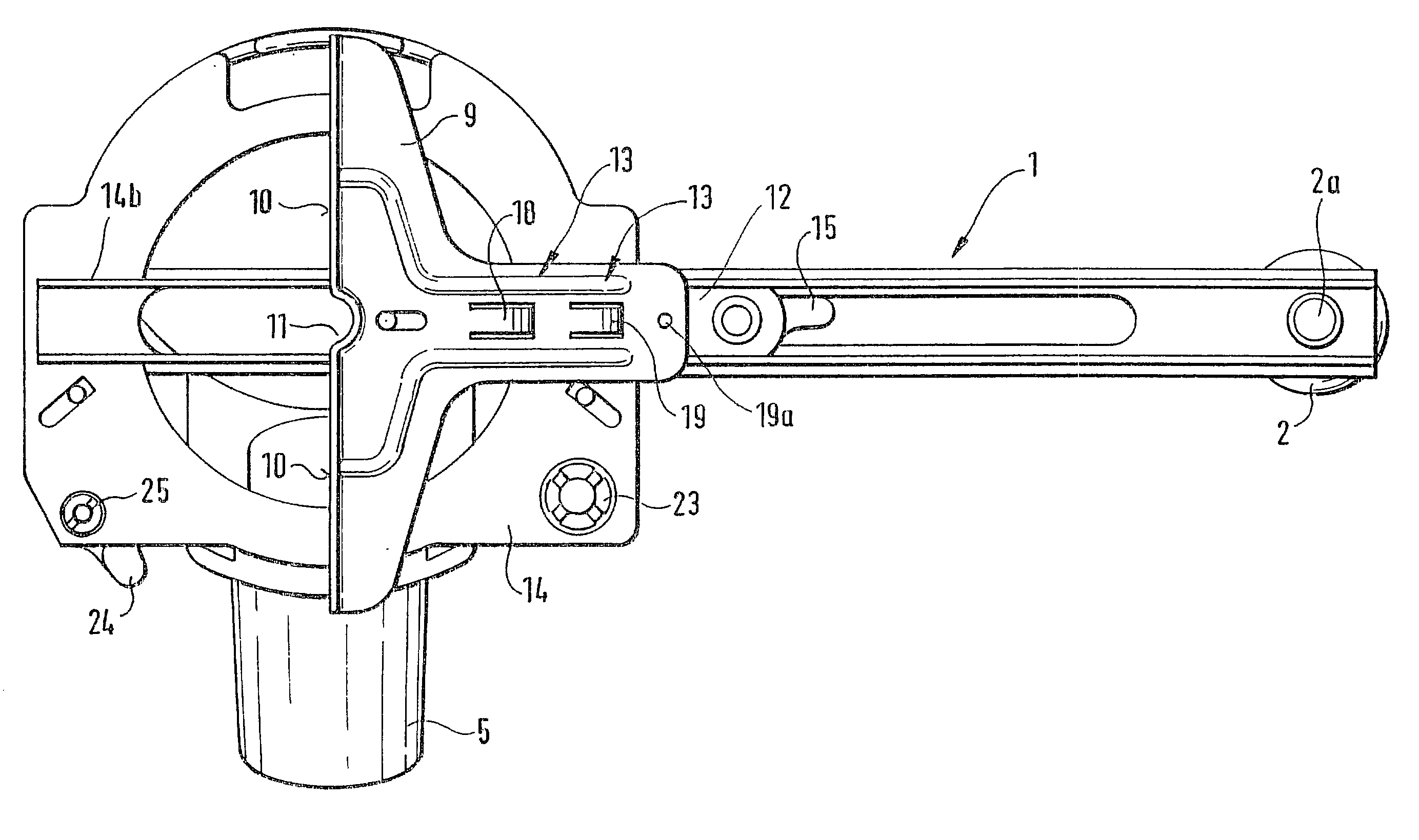
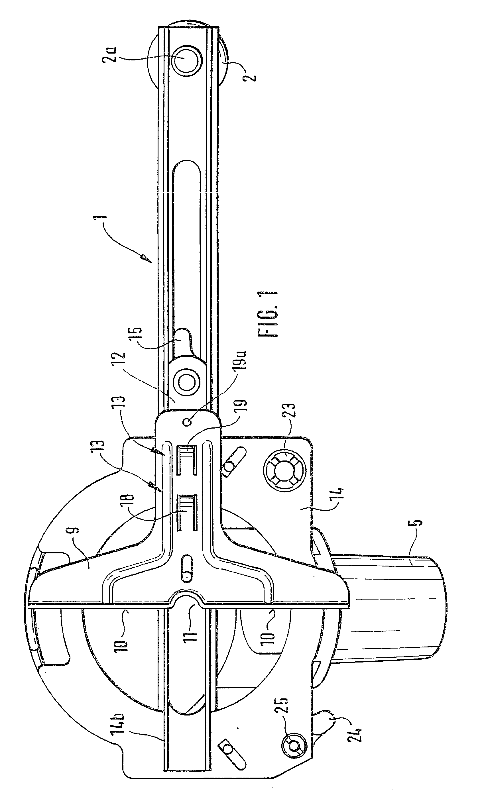
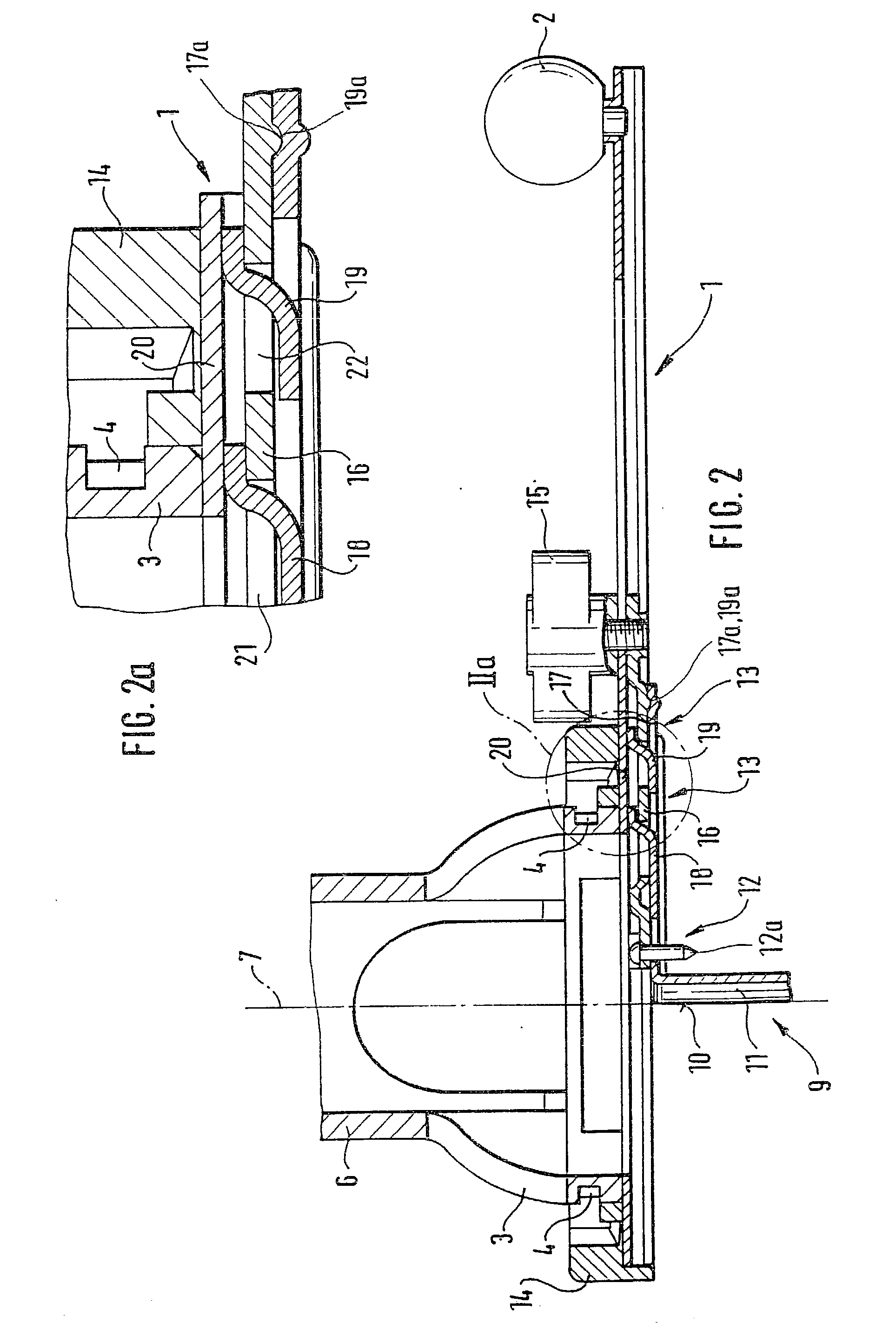
[0004] Numerous advantages for operator using the electric hand tool, which is improved according to the invention, can be inferred from the embodiment proposed according to the invention. The function of an electric hand tool with an electric drive unit can be expanded in a multi-faceted way simply through the detent locking the mounting section of a mounting rail.
[0005] On the mounting rail itself, which can be comprised of U-shaped profiles that are slid into each other and are made of a metallic material or also of plastic, a compass point is provided on a carriage-shaped component and locking mechanisms are provided for the installation of a parallel fence. The parallel fence, which can be comprised of metal or shock-resistant plastic, can be fixed in its respective operating position on the mounting rail by means of a half turn or a three-quarter turn of a locking screw. The guide surface of the parallel fence is interrupted approximately in the middle by a recess, which in se...
PUM
 Abstract
Description
Claims
Application Information