Optical monitoring processes and apparatus for combined liquid level sensing and quality control

a technology of optical monitoring and liquid level sensing, applied in liquid handling, instruments, packaged goods types, etc., can solve the problems of significant health hazards, degradation cannot be tolerated in critical semiconductor manufacturing steps, and many semiconductor manufacturing processes involve very expensive chemicals

Inactive Publication Date: 2003-01-16
LAIR LIQUIDE SA POUR LETUDE & LEXPLOITATION DES PROCEDES GEORGES CLAUDE +1
View PDF0 Cites 17 Cited by
  • Summary
  • Abstract
  • Description
  • Claims
  • Application Information

AI Technical Summary

Problems solved by technology

To make matters worse, many semiconductor manufacturing processes involve very expensive chemicals which have significant health hazards associated with them.
Such degradation cannot be tolerated in critical semiconductor manufacturing steps because extremely high purity chemicals are required.
Many organometallic compounds used in chemical vapor deposition are reactive in nature and are difficult to obtain in pure form commercially.
In chemical vapor deposition processes, it is advantageous if the liquid chemicals are easily degraded at lower process temperatures; however, this leads to the use of less thermally stable compounds.
Furthermore, such compounds react with trace moisture and numerous other sources of oxides to form insoluble metal oxides that become suspended in the liquid causing the liquid to become turbid.

Method used


Image

  • Optical monitoring processes and apparatus for combined liquid level sensing and quality control
  • Optical monitoring processes and apparatus for combined liquid level sensing and quality control
  • Optical monitoring processes and apparatus for combined liquid level sensing and quality control

Examples


second embodiment

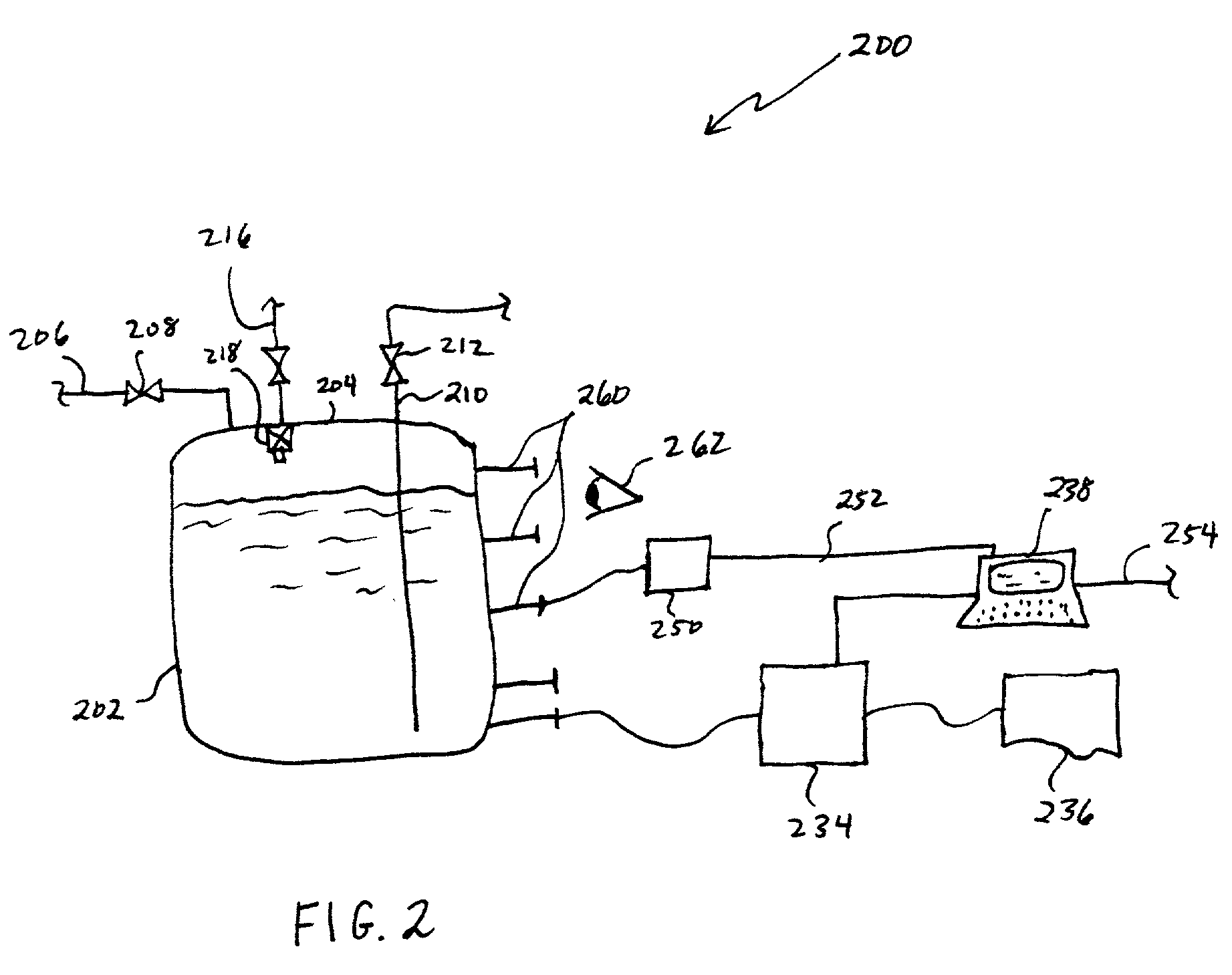
[0036] In a second embodiment, use of optical monitoring "level sensing" fibers that extend out of the sides of the liquid chemical container are used to monitor both intensity for liquid level, as in the present design, and also spectral profile for chemical color or turbidity characteristics for quality / purity information.

third embodiment

[0037] A third embodiment employs a single optical feed through connection, preferably made on or near the top of the container, and light propagation directed perpendicularly to the liquid surface. Using more sophisticated spectral interpretation of light from the fibers, both liquid level and chemical purity can be assessed. Such installation minimizes manufacturing costs as well as limits the number of container seals required, thereby reducing potential sites for leaks and chemical degradation from sealing materials required in the optical connections to the container.

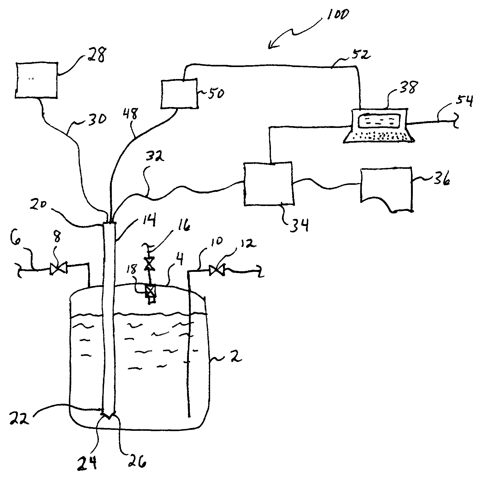
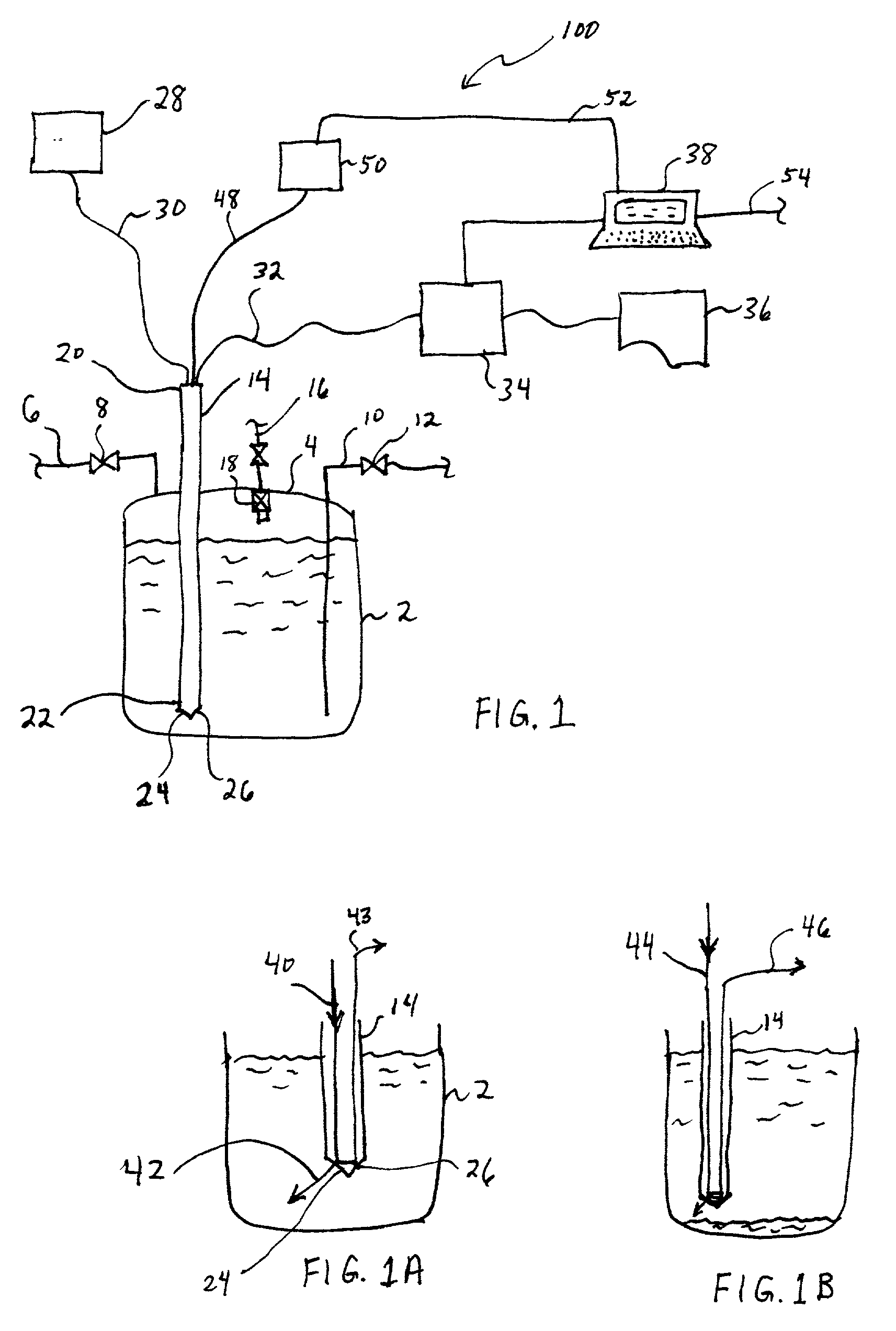
[0038] Referring now to the drawing figures, FIG. 1 illustrates a first embodiment 100 of an apparatus in accordance with the invention. Apparatus 100 includes a container 2 having a container top 4, a liquid inlet conduit 6 and control valve 8, and a liquid chemical outlet conduit 10 and control valve 12. Present is an optical element 14, an optional gas inlet 16 with gas filter 18, gas filter 18 preferably compri...

embodiment 100

[0043] FIG. 3 illustrates another embodiment of an apparatus in accordance with the present invention, illustrating a container 302 having liquid chemical inlet conduit 306 and control valve 308, and liquid chemical outlet conduit 310 and control valve 312. An optional gas inlet conduit 316 is illustrated, as well as optional gas filtration media cartridge 318. Container 302 has a top 304, through which an optical member 314 protrudes. While this is similar to the embodiment 100 in FIG. 1, note that distal end 322 does not protrude into or contact liquid within container 302. Optical member 314 is connected via optical fiber 330 to a light source 328. Light that is transmitted or reflected through optical member 314 indicating liquid level is transmitted through an optical fiber 348 into light receptor 350, which may have an output via connection 352 to computer 338. Simultaneously, quality determination of liquid within container 302 may be obtained through optical fiber 332 connec...


PUM

PropertyMeasurementUnit
concentrationaaaaaaaaaa
optical propertiesaaaaaaaaaa
optical discriminationaaaaaaaaaa

Abstract

Methods and apparatus of measuring both concentration and amount of a liquid in a liquid chemical container are presented, one method comprising the steps of: (a) viewing light emanating from a first optical member that is in visual contact with the liquid, the light emanating from the optical member having a level indicating quality; and (b) routing light from a second optical member that is in visual contact with the liquid to means for optical discrimination between liquid chemical based on different optical properties.

Description

[0001] 1. Field of the Invention[0002] This invention relates generally to liquid level detection, and more specifically to optical liquid level detection, wherein quality of the liquid chemical is also determined.[0003] 2. Related Art[0004] There are many processes involving liquid chemicals which require consistent and reliable delivery of liquid chemicals with very high purity. In the semiconductor manufacturing industry, for example, reliable delivery of high purity liquids to the process chamber is critical to the overall operation. Catastrophic process events can occur, for example, if liquid levels in canisters or ampoules are not monitored accurately. To make matters worse, many semiconductor manufacturing processes involve very expensive chemicals which have significant health hazards associated with them. These factors require good utilization of the chemical involved along with minimal waste. As a result, there is a need for reliable level sensing of liquid source and int...

Claims


Application Information

Patent Timeline
Patent Type & Authority Applications(United States)
IPC IPC(8): G01F23/292
CPCG01F23/2927Y10T137/2509
Inventor JURSICH, GREGORY M.SIRK, KEVIN
Owner LAIR LIQUIDE SA POUR LETUDE & LEXPLOITATION DES PROCEDES GEORGES CLAUDE
Why Eureka
Try Eureka