UV radiation device for treating fluids with a simplified radiation chamber

a radiation device and simplified technology, applied in the direction of instruments, chemical/physical/physico-chemical processes, water/sludge/sewage treatment, etc., can solve the problems of reducing the cost of the radiation device itself as well as the transportation and assembly costs necessary, and the device represents a relatively high technical cos

Inactive Publication Date: 2003-01-16
WEDECO WATER TECH
View PDF7 Cites 36 Cited by
  • Summary
  • Abstract
  • Description
  • Claims
  • Application Information

AI Technical Summary

Problems solved by technology

This known radiation device restricts the cross-section of the waste water conduit which is often undesirable for hydrodynamic reasons.
In addition, these devices represent a relatively high technical expense not required by the function of the radiation process itself.
This configuration is in practice also seen as disadvantageous since the radiation sources with the tot

Method used


Image

  • UV radiation device for treating fluids with a simplified radiation chamber
  • UV radiation device for treating fluids with a simplified radiation chamber

Examples


Embodiment Construction

[0017] While this invention is susceptible of embodiment in many different forms, there is shown in the drawings and will be described in detail, specific embodiments with the understanding that the present disclosure is to be considered as an exemplification of the principles of the invention and is not intended to limit the invention to the embodiments illustrated.

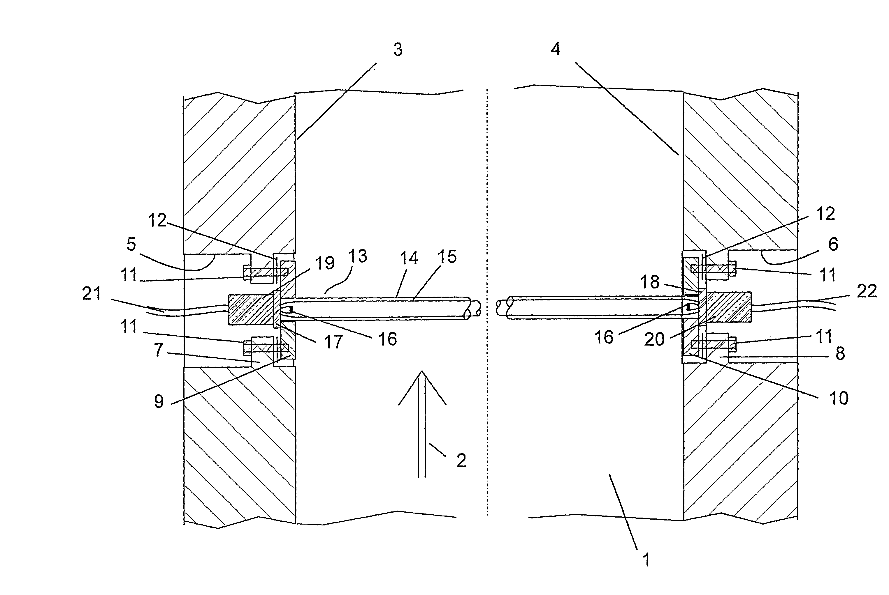
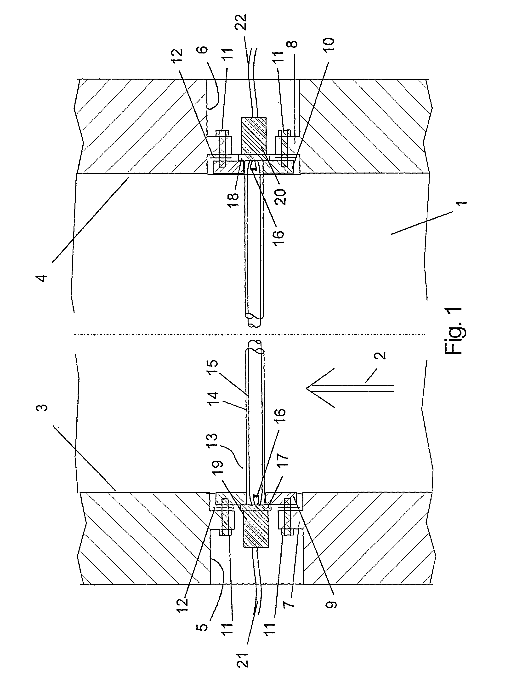
[0018] FIG. 1 shows a radiation chamber of a UV radiation device as a cross-sectional view taken from above.

[0019] The radiation chamber is bordered on its underneath by a base wall 1 and in relation to a flow direction 2 by a left side wall 3 and a right side wall 4. The side walls 3 and 4 in each case have a recess 5, 6 supporting bridges moulded in one-piece 7, 8 which run in the vertical direction. The bridges 7, 8 hold flange plates 9, 10, inserted from the inside of the radiation chamber which are connected with the side walls 3, 4 by means of threaded screws 11 from the outside with a flexible rubber gasket 12 ins...


PUM


Abstract

The invention relates to a UV radiation device for the treatment of fluids, in particular water or waste water. The device includes a radiation chamber through which the fluid can flow in one direction. The radiation chamber essentially comprises a rectangular cross-section and is bordered by two side walls as well as a base wall and a ceiling wall. The side walls and the base wall comprise a non-metallic material. Additionally, a number of lamp units are provided. The lamp units each have a radiation source and a cover tube surrounding the radiation source, and, the lamp units are essentially cylindrical in shape. The lamp units lamp units in at least one cross-direction are arranged towards the flow direction. The distance between two walls diagonally facing each other is less or equal to the discharge length of the radiation source.

Description

[0001] 1. Field of the Invention[0002] The present invention relates to UV radiation devices, and in particular to a UV radiation device for treating fluids with a simplified radiation chamber.[0003] 2. Background Art[0004] UV radiation devices are known in the art. For example, one UV radiation device is shown in U.S. Pat. No. 4,367,410. There an arrangement, formed from two bulkhead walls and a radiation chamber lying in between which reduces the cross section of the waste water conduit so that the waste water flow to be treated must enter the radiation chamber, is inserted in a gulley of a waste water conduit. A number of lamp units are arranged diagonally to the flow direction in the radiation chamber. The lamp units are in each case arranged above each other in rows in relation to the flow direction. Several rows of lamp units are arranged behind each other in relation to the flow direction.[0005] This known radiation device restricts the cross-section of the waste water condui...

Claims


Application Information

Patent Timeline
IPC IPC(8): A61L2/10C02F1/32G21K5/10
CPCA61L2/10C02F1/325C02F2201/3227G21K5/10
Inventor WEDEKAMP, HORST
Owner WEDECO WATER TECH
Why Eureka
Try Eureka